Optical inspection scope with deformable, self-supporting deployment tether

a deployment tether and optical inspection technology, applied in the field of video/camera inspection systems, can solve the problems of affecting the stability of the camera field of view, risking potential damage to relatively brittle and fragile surfaces, etc., and achieve the effect of facilitating the insertion of the tether

Inactive Publication Date: 2015-11-26
SIEMENS ENERGY INC
View PDF7 Cites 18 Cited by
  • Summary
  • Abstract
  • Description
  • Claims
  • Application Information

AI Technical Summary

Benefits of technology

[0011]Other exemplary embodiments of the invention feature a method for internal non-destructive inspection of areas of interest within a power generation machine. The provided power generation machine has areas of interest therein that are in communication with corresponding internal passages. The passages are externally accessible from outside the machine. A video inspection scope is provided, which includes a self-supporting and shape retaining, elongate deformable tubular deployment tether having distal and proximal ends. The tether is constructed of a metallic inner tube, defining a lumen therethrough that is radially circumscribed by a polymeric outer layer that is bonded thereto. A camera head is coupled to the distal end of the deployment tether. A video camera (or other reflective-photonic, optical inspection instrument), is coupled to the camera head, for capturing video images within a camera field of view. A video control system is coupled to the video camera, and receives camera video images for further processing. During the inspection process, a first internal area of interest is inspected within the provided power generation machine by bending the metallic inner tube to conform elongate profile of the deployment tether to a first deformation profile. The bent first profile facilitates insertion of the tether and camera head proximate the first internal area of interest through a corresponding internal passage that is in communication with the area of interest. The first deformation profile deployment tether and camera head are inserted into the corresponding internal passage, so that the camera head is proximate the first area of interest. Movement of the deployment tether proximal end orients the camera field of view to include the first area of interest, and an image of the area of interest is captured by the camera. The captured image is transferred to the video control system.

Problems solved by technology

Rigid tube borescopes are not insertable in twisting or tightly confined cavities within power generation machinery.
Flexible tether borescopes are not self-supporting, so the camera field of view stability is disrupted by inadvertent tether movement, such as if the tether inadvertently slips during video inspection.
Flexible tether borescopes inadvertently contact internal surfaces within power generation machinery as they are maneuvered through internal machinery passages, risking potential damage to relatively brittle and fragile surfaces, such as thermal barrier coatings on turbine engine blades, vanes or combustor transitions.

Method used


Image

  • Optical inspection scope with deformable, self-supporting deployment tether
  • Optical inspection scope with deformable, self-supporting deployment tether
  • Optical inspection scope with deformable, self-supporting deployment tether

Examples


Embodiment Construction

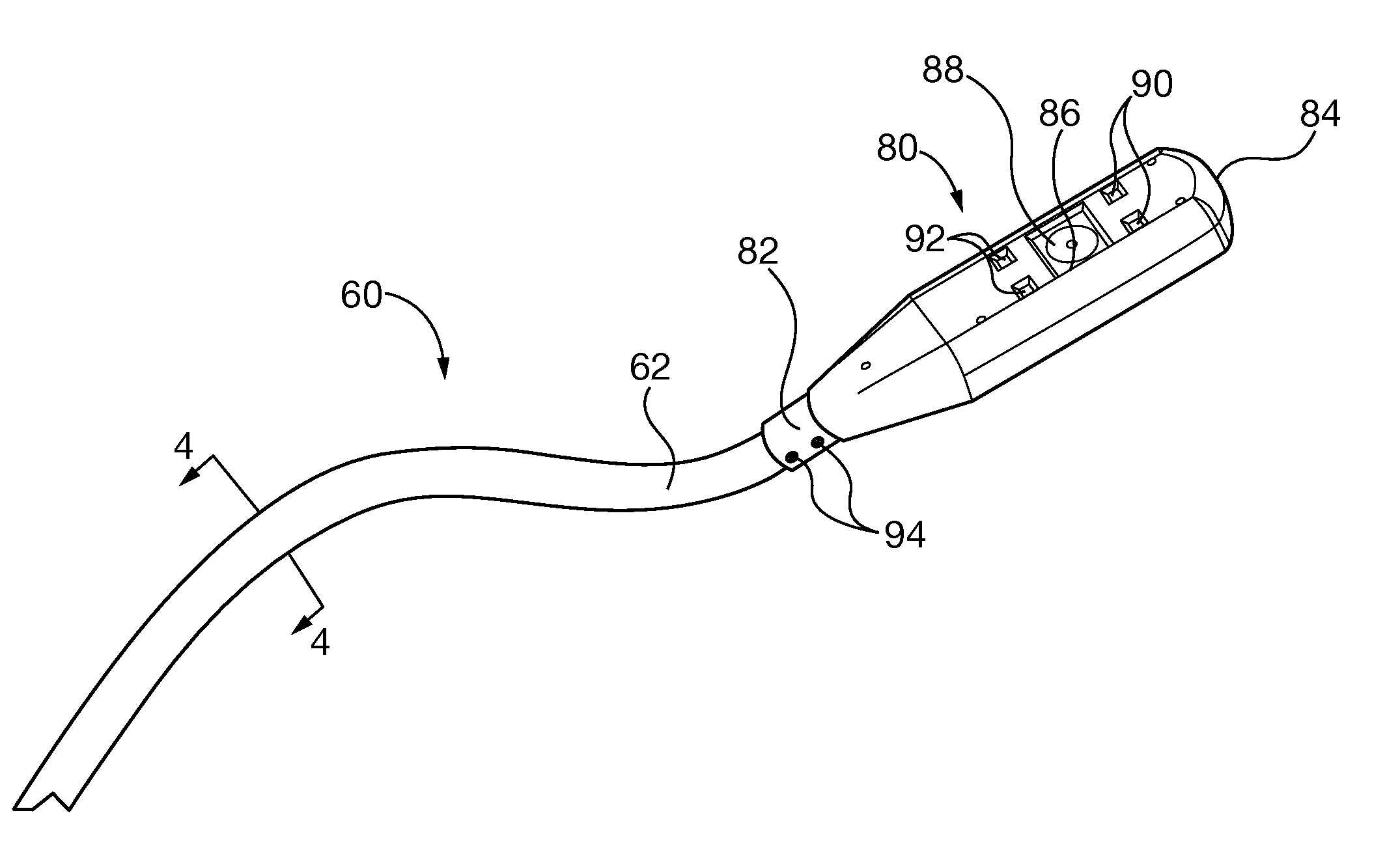
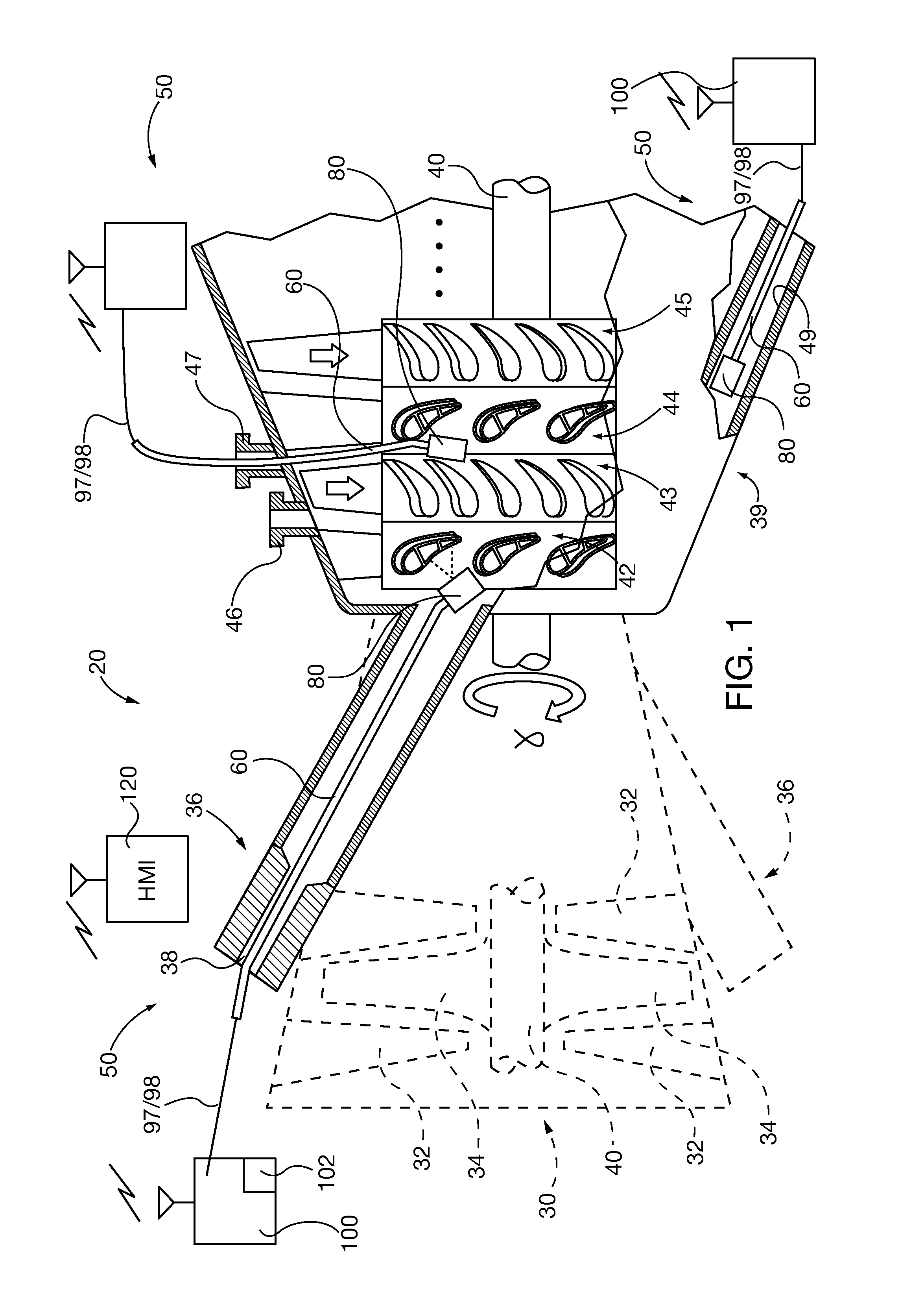
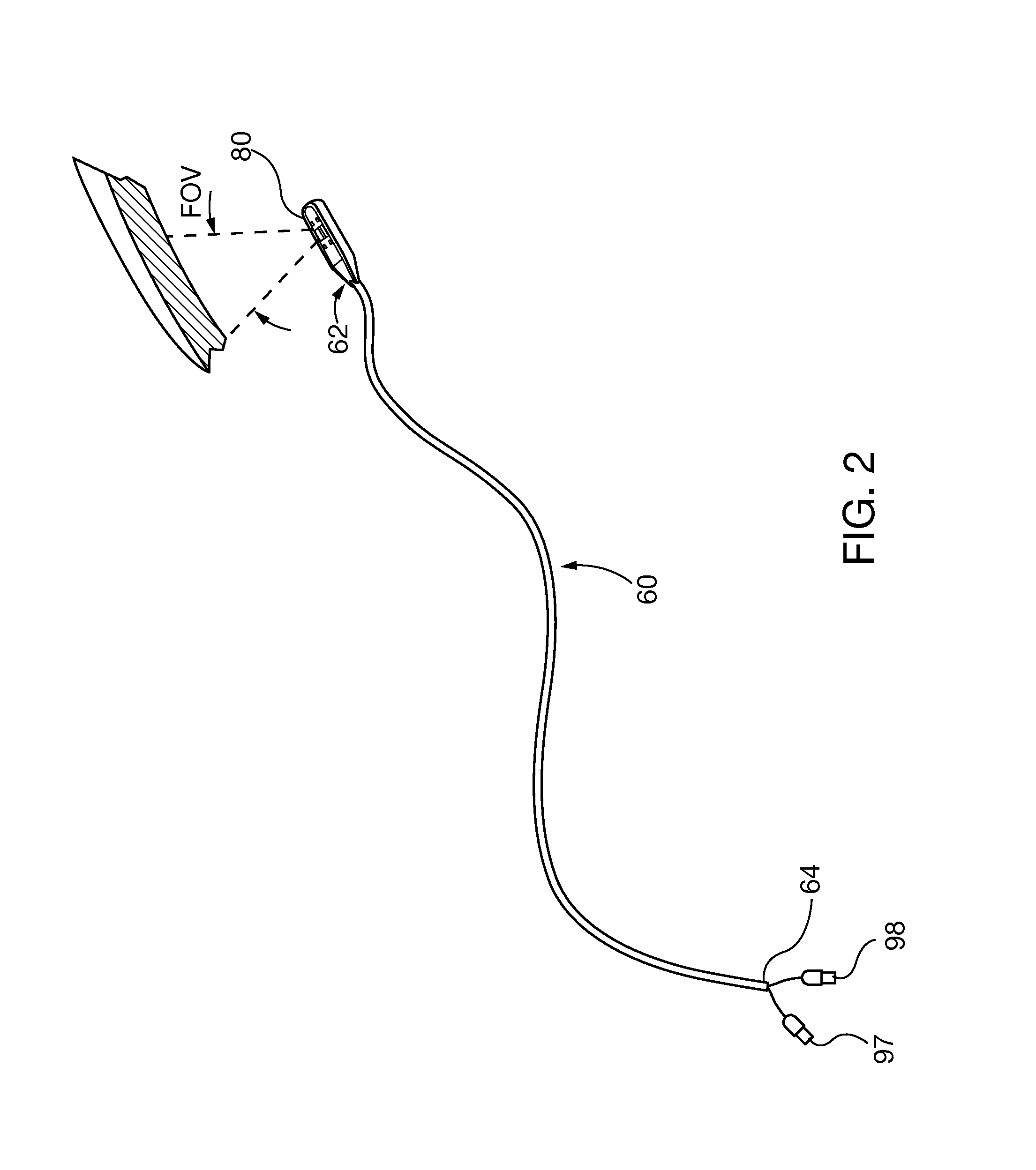
[0023]Exemplary embodiments of the invention are utilized in non-destructive evaluation optical inspection systems. The system includes video cameras or other reflective-photonic optical instruments, such as laser profilometers or 3D white light laser dimensional scanners, which are incorporated in a camera head. The camera head is coupled to a distal end of a self-supporting and shape-retaining elongate deformable deployment tether. The deployment tether is bendable, for insertion through cavities of power generation machines and orientation of the camera head field of view on the internal area of interest. The deployment tether is capable of being deformed repeatedly, for inspection of different areas of interest. Unlike known rigid tube borescopes, the deformable deployment tether used in embodiments of the invention can be bent to conform to tortuous insertion paths within power generation machinery internal cavities. Unlike known flexible tube borescopes, the deformable deploym...


PUM

PropertyMeasurementUnit
temperaturesaaaaaaaaaa
areasaaaaaaaaaa
areaaaaaaaaaaa

Abstract

Non-destructive evaluation optical inspection systems include video cameras or other reflective-photonic optical instruments, such as laser profilometers or 3D white light laser dimensional scanners, which are incorporated in a camera head. The camera head is coupled to a distal end of a self-supporting and shape-retaining elongate deformable deployment tether. The deployment tether is bendable, for insertion through cavities of power generation machines and orientation of the camera head field of view on the internal area of interest. The deployment tether is capable of being deformed repeatedly, for inspection of different areas of interest. In some embodiments, interchangeable camera heads are selectively coupled to the deployment tether, so that a kit or family of different optical inspection instruments are available to carry out multiple types of inspections within a single or multiple types of power generation machinery.

Description

CROSS-REFERENCE TO RELATED APPLICATIONS[0001]This application is a continuation-in-part of United States utility patent application entitled “System And Method For Visual Inspection And 3D White Light Scanning Of Off-Line Industrial Gas Turbines And Other Power Generation Machinery”, filed, Aug. 21, 2013 and assigned Ser. No. 13 / 972,000; which in turn claims the benefit of United States provisional patent application entitled “Hybrid Scope—Turbine Combustor Hardware Visual Inspection Tooling That Can Also Be Used To Inspect The Row 1 Turbine Blades While They Are On Turning Gear (1-1000 rpm)” filed Aug. 23, 2012 and assigned Ser. No. 61 / 692,393 and United States provisional patent application entitled “Vision Scope—3D Scanner Tip for Visual Inspection and Measurement” filed Aug. 23, 2012 and assigned Ser. No. 61 / 692,409; and which is also a continuation-in-part of United States utility patent application entitled “System And Method For Automated Optical Inspection Of Industrial Gas ...

Claims


Application Information

Patent Timeline
Patent Type & Authority Applications(United States)
IPC IPC(8): G01N21/954G01M15/14H04N5/232G01M15/02H04N7/18H04N5/225
CPCG01N21/954H04N7/183H04N5/2253H04N5/23293G01N2021/9544G01M15/02G01M15/14H04N2005/2255H04N5/2252F01D21/003G02B23/2484H04N23/50H04N23/51H04N23/54H04N23/555
Inventor BANCALARI, ALEJANDROHATCHER, JR., CLIFFORDRUHGE, FORREST R.WILLIAMS, JAMES P.DEASCANIS, JOSHUALETTER, DAVIDSHANNON, ROBERT G.
Owner SIEMENS ENERGY INC
Why Eureka
Try Eureka