Mechanical devices and method of creating prescribed vibration

a mechanical device and vibration technology, applied in the direction of mechanical vibration separation, dynamo-electric converter control, motor/generator/converter stopper, etc., can solve the problem that the above-mentioned device cannot create certain desirable vibration profiles, the above-mentioned device cannot create a variety of selectable vibration profiles within limits, and the above-mentioned device cannot maintain a desired vibration profile. , to achieve the effect of reducing the difference between the measured

Inactive Publication Date: 2015-11-26
LORD CORP
View PDF9 Cites 14 Cited by
  • Summary
  • Abstract
  • Description
  • Claims
  • Application Information

AI Technical Summary

Benefits of technology

[0011](f) communicating the changes to the force vector to the CFG such that the difference between the measured operating function and the prescribed operating function is reduced.

Problems solved by technology

The aforementioned devices are incapable of maintaining a desired vibration profile when operating conditions change, such as a change in material loading, changes in temperature, changes in material properties, or other variables that can alter the response of the mechanical device.
In some cases, the aforementioned devices cannot create certain desirable vibration profiles.
In other cases, the aforementioned devices cannot create a variety of selectable vibration profiles within limits imposed by the authority of their respective force generators.

Method used


Image

  • Mechanical devices and method of creating prescribed vibration
  • Mechanical devices and method of creating prescribed vibration
  • Mechanical devices and method of creating prescribed vibration

Examples


Embodiment Construction

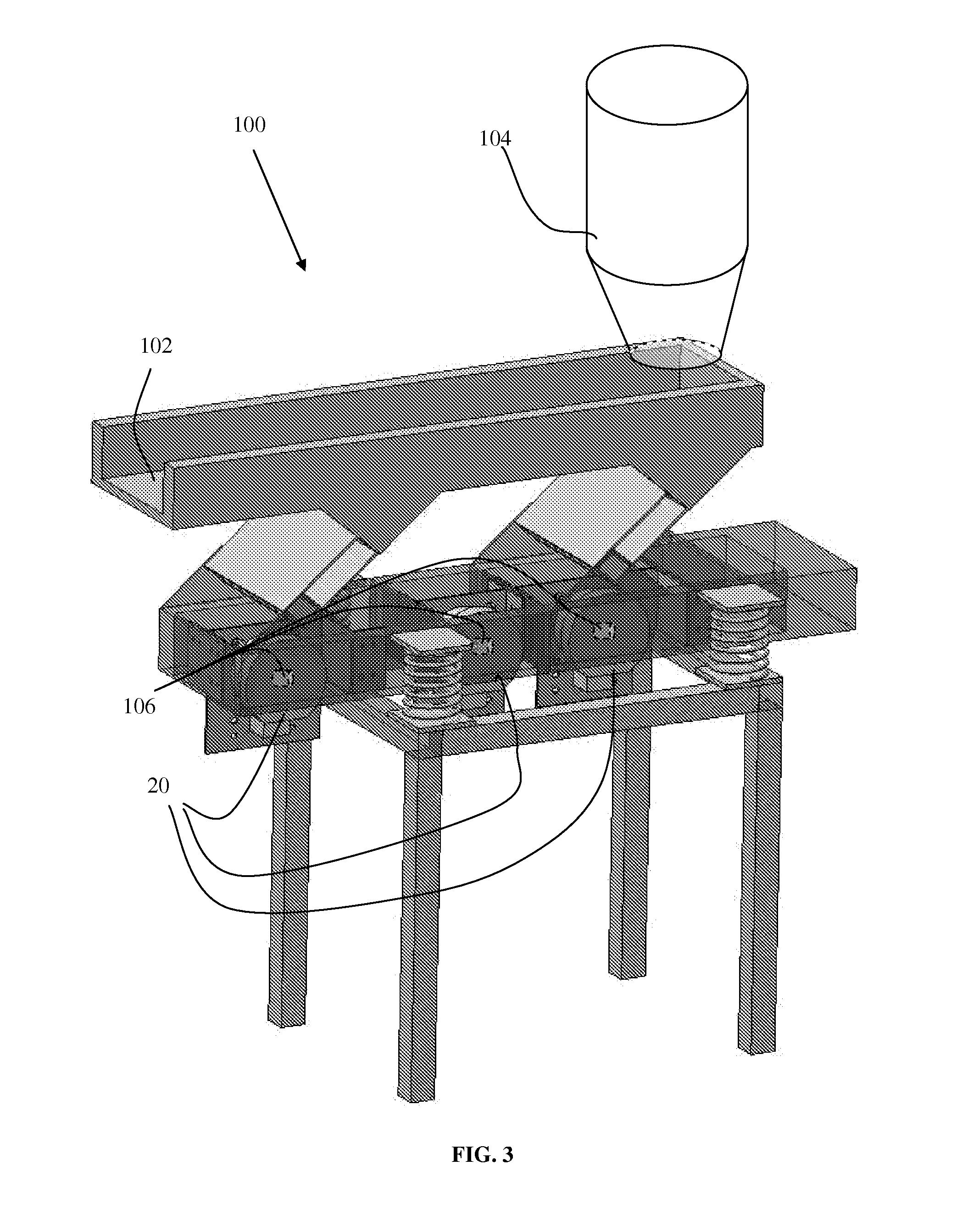
[0024]The invention described herein is applicable to a wide range of devices where a mechanically induced vibration is desired, the non-limiting examples of vibratory deliquifying machines, conveyors, and separators are used for illustration purposes.

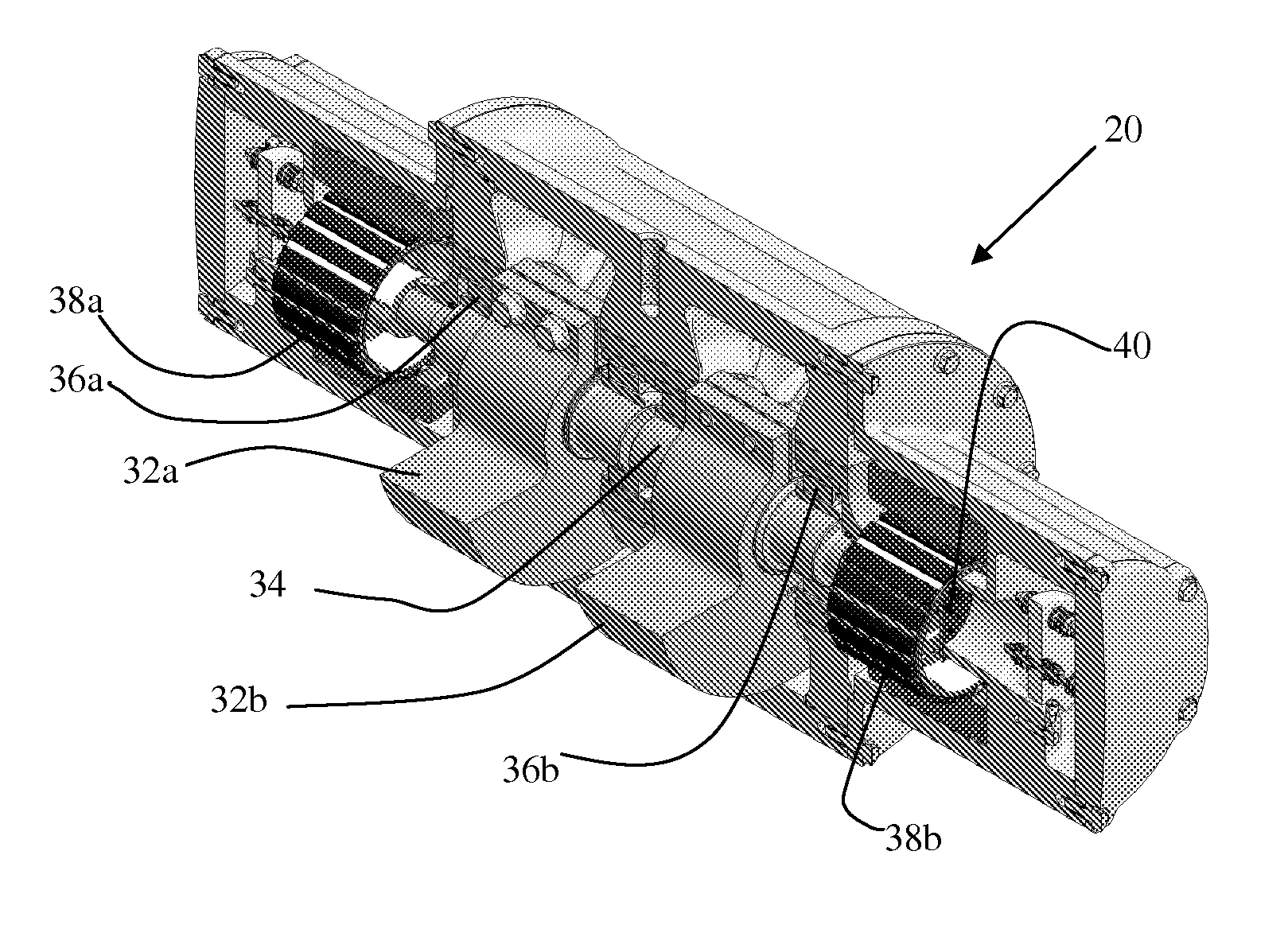
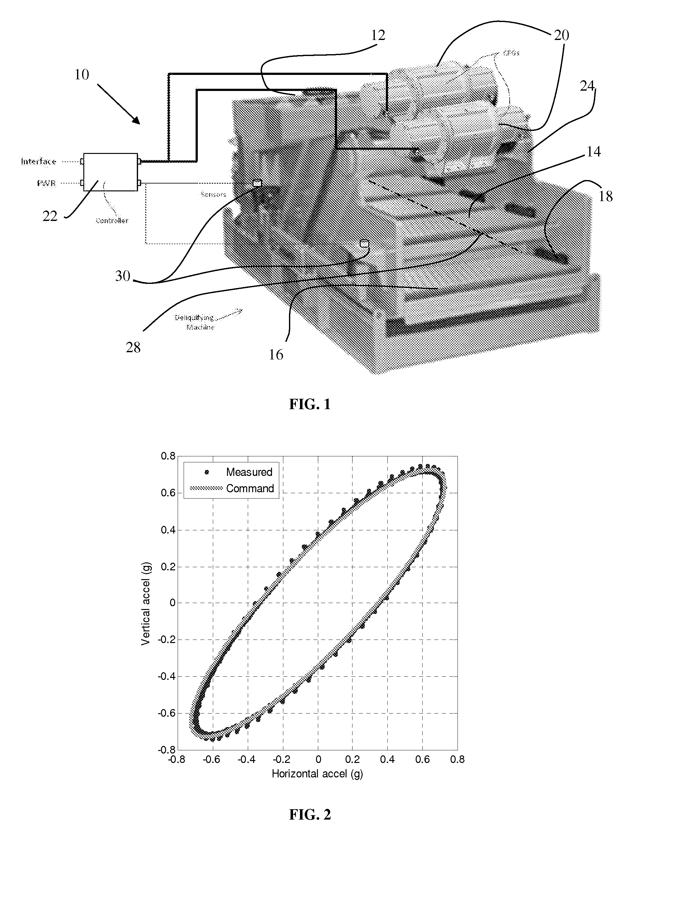
[0025]Referring to the drawings, FIG. 1 shows the invention as applied to the non-limiting example of a vibratory deliquifying machine illustrated and generally designated by the numeral 10. The non-limiting example vibratory deliquifying machine 10, as illustrated, includes inlet 12, screen 14, exit 16, springs 18, and force generators 20. Force generators 20 are preferably CFG 20.

[0026]In vibratory deliquifying machine 10, slurries (not shown) enter inlet 12 where a vibratory motion causes the slurry to convey across screen 14 suspended on springs 18. As the slurry is conveyed across screen 14, liquid passes through screen 14 while dry material (not shown) is extracted at exit 16.

[0027]Existing vibratory deliquifying machines 10 have...


PUM


Abstract

The invention provides a system for creating a prescribed vibration profile on a mechanical device comprising a sensor (30) for measuring an operating condition of the mechanical device, a circular force generator CFG (20) for creating a controllable rotating force vector comprising a controllable force magnitude, a controllable force phase and a controllable force frequency, a controller (22) in electronic communication with said sensor and said circular force generator, the controller operably controlling the controllable rotating force vector, wherein the difference between the measured operating condition and a desired operating condition is minimized.

Description

[0001]Some mechanical devices perform specific functions through use of induced vibratory motion. Such devices include monitoring damage detection and structural assessment of civil structures and mechanical devices, damping in civil structures, searching for oil and gas with seismic impulse exciters, medical device and equipment, controlling fluid flow in a pipe, deliquifying screens, material separators, vibratory feeders and conveyors, attrition mills, mold shakeout machines, and vibratory compactors. Typically these devices utilize one or more force generators to create a predefined force profile for inducing vibration within the device. These force generators may include linear drives or imbalanced rotors driven by synchronous motors or induction motors whose speed is an integer fraction of the electrical source frequency. To vary the frequency of vibration, variable frequency drives (VFDs) are used in conjunction with these motors. To tailor the shape of the vibration profile ...

Claims


Application Information

Patent Timeline
Patent Type & Authority Applications(United States)
IPC IPC(8): H02P25/02
CPCH02P25/027B06B1/161H02P25/032
Inventor JOLLY, MARK R.ALTIERI, RUSSELL E.BADRE-ALAM, ASKARIOWENS, JONATHAN M.HUNTER, ANTHONYJONES, BRADLEY N.CARR, BRIANHOLTON, BENCADY, ERIC
Owner LORD CORP
Why Eureka
Try Eureka