Method and system for imaging

a technology of imaging and system, applied in the field of imaging method and system, can solve the problems of not being able to image the lung with sufficient spatial and temporal resolution, affecting the airflow during breathing, altering the normal motion of the lung,

Inactive Publication Date: 2016-12-08
MONASH UNIV
View PDF0 Cites 5 Cited by
  • Summary
  • Abstract
  • Description
  • Claims
  • Application Information

AI Technical Summary

Benefits of technology

[0016]An object of the present invention is to provide improved technology for assessing lung function and diagnosing lung conditions.
[0033]The lung responds to an oscillating input to the airway opening via movement of the lung tissue. This movement can potentially reveal detailed information regarding the state and function of the lungs. In the present invention, the oscillation provided to the lung may be of a single frequency, but typically multiple frequencies will be used. The frequencies could be provided simultaneously or one after the other. Oscillations can either be measured at many images per cycle of lowest frequency or an ensemble type average recorded over many cycles, therefore capable of being recorded at a slower rate than the input oscillations.
[0049]The pressure in the ventilator may be controlled by any convenient means. For example, in one embodiment the pressure may be controlled through a sequence of measurements (via sensors) and adjustment of valves controlled through a computer interface and software. In another more preferred embodiment, the ventilator pressure may be controlled through a feedback sequence, which in turn is controlled locally by a microprocessor within the ventilator. The latter embodiment provides a much faster and more stable system.
[0068]Alternatively the pressure can be maintained by the feedback control system. As the feedback control system performance is increased, smaller pressure vessels will be required.
[0072]improved spatial and temporal resolution for assessing lung function and diagnosing lung conditions;
[0076]improved identification of subtle changes of structure in (such as during the early stages of a disease or other disorder);

Problems solved by technology

Lung diseases adversely affect airflow during breathing and alter normal lung motion.
Although this information is best provided by imaging the lung in situ, it has not hitherto been possible to image the lung with sufficient spatial and temporal resolution.
One of the drawbacks of this technology is that it cannot measure response locally with in the lungs and as a result it is unable to detect any but the largest physiological changes in the lungs.
Due to the global nature of FOT and the potential of destructive interference between different signals in lung regions there is the likelihood that this approach will result in lost information.
Standard imaging techniques such as X-ray Computer Tomography (CT) and Magnetic Resonance Imaging (MRI) imaging during breath-holds provide little or no information on lung motion and cannot detect disease that cause subtle changes in lung structure.
These approaches are particularly limited by the need to image the lung while it is stationary to minimise blurring.
In particular, MRI and CT have poor temporal resolution preventing them from being used to image the lungs during a dynamic lung test.
This has obvious drawbacks and limits the ability of the techniques to be used for dynamic lung function testing.
This results in poor temporal resolution for investigation for the dynamic patterns of motion and expansion within the lung, particularly for small animal studies.
This technique however, suffers from very poor spatial resolution and is based on measurements taken through the chest wall resulting in poor dynamic range of measurements.
EIT provides information through a horizontal slice of the lung, is easily affected by the electrical signals of the heart and has very poor spatial resolution.
Despite advances in lung imaging, altered patterns of lung motion have not hitherto been utilised for disease detection.

Method used


Image

  • Method and system for imaging
  • Method and system for imaging
  • Method and system for imaging

Examples


Embodiment Construction

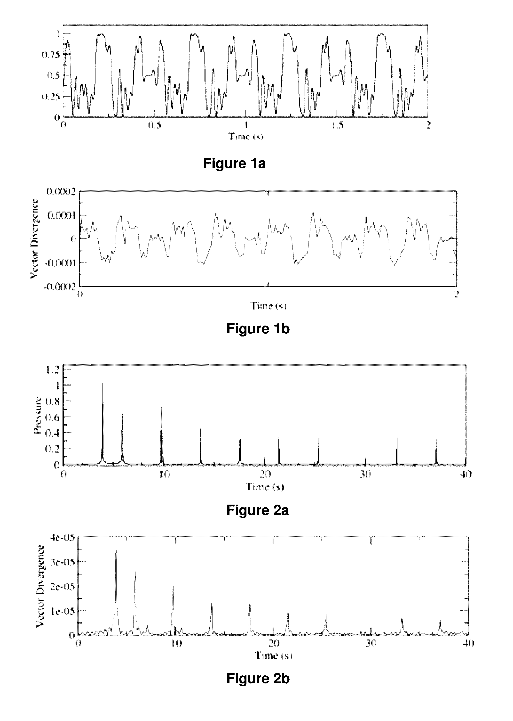
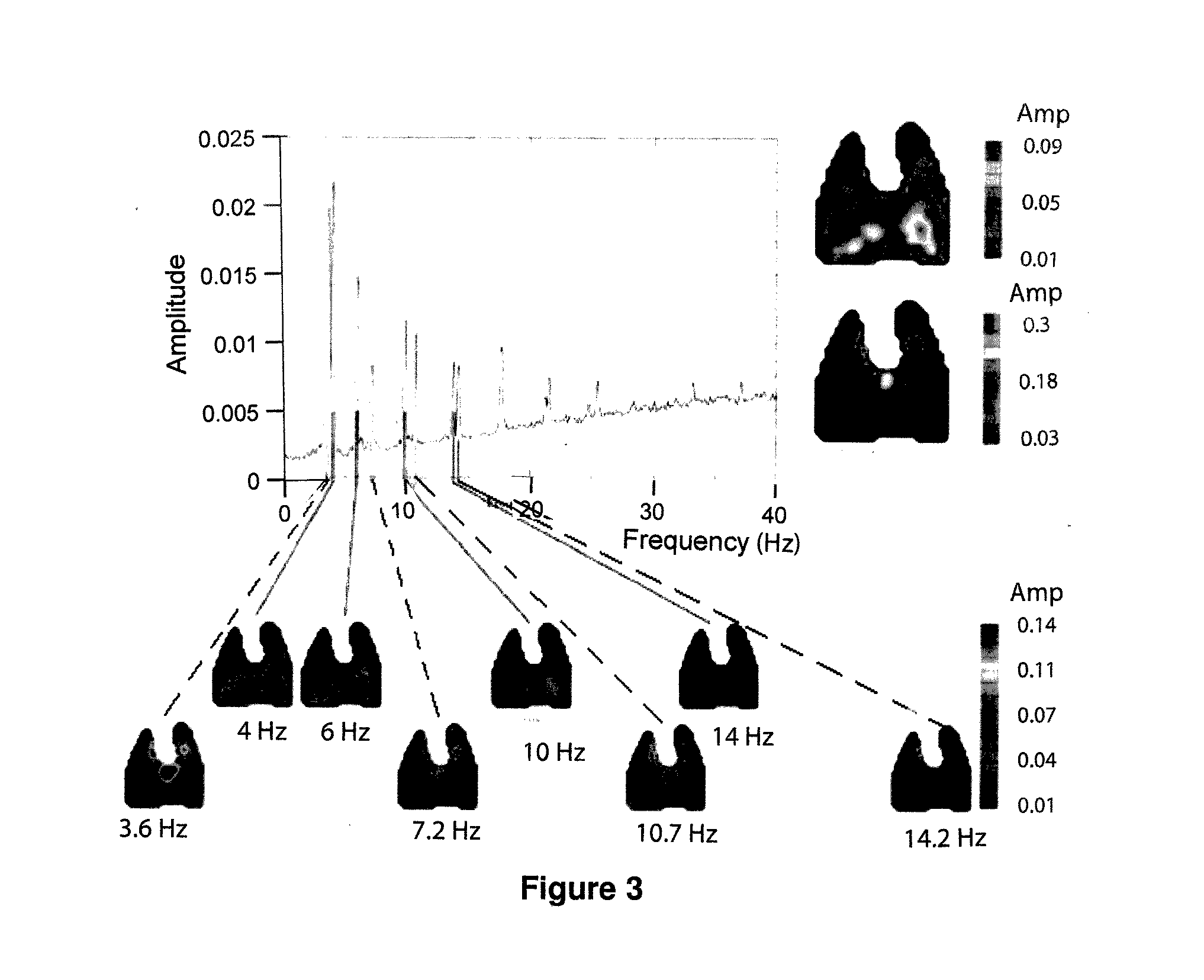
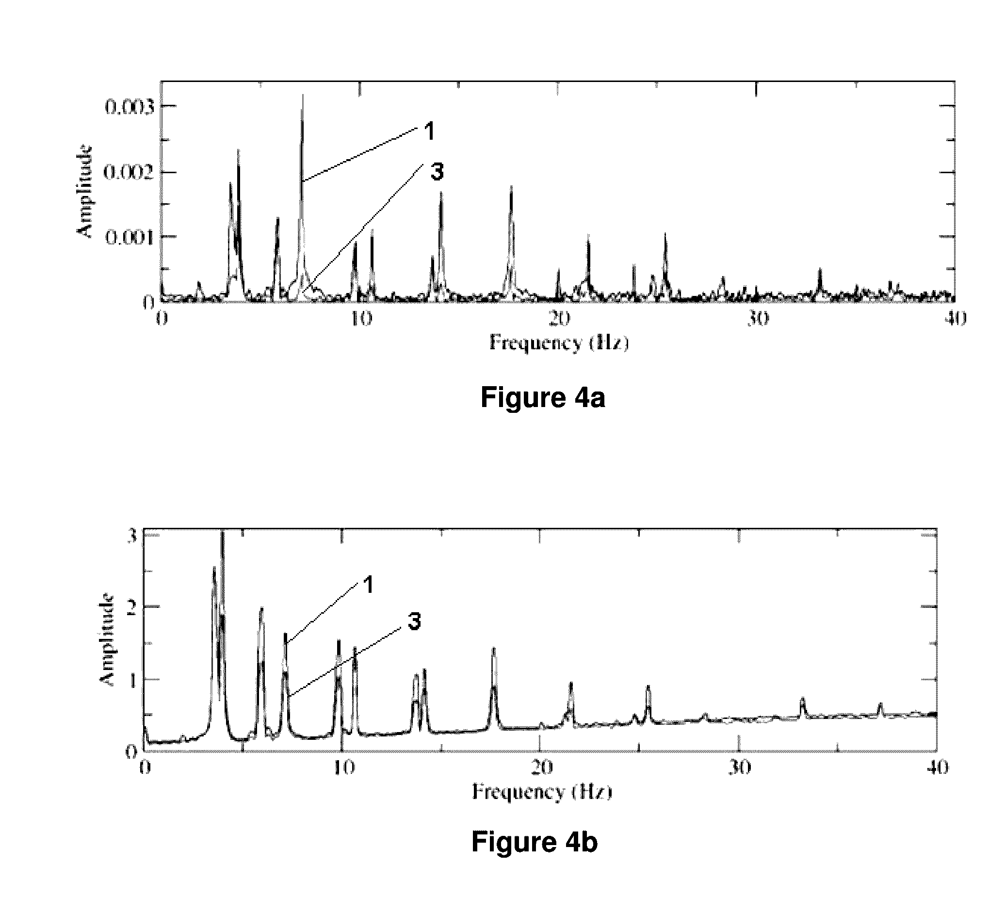
[0125]Although many different imaging methods are suitable for use in the present invention, in a particularly preferred embodiment the present invention uses phase-contrast x-ray imaging (PCXI). PCXI exploits the phase change caused by x-ray refraction when passing between media of differing refractive indices to produce high contrast images of the lung. Interference between transmitted and refracted x-rays produces high contrast images of the air / tissue boundaries compared with conventional x-ray absorption techniques. It is able to achieve this because the phase shift of the x-rays is generally more than three orders of magnitude greater than the absorption over the diagnostic x-ray energy range (20 keV-90 keV). An important consequence of this is that phase-contrast images can be recorded with significantly lower dose than conventional images, which is particularly important for both longitudinal studies and dynamic studies where repeated imaging is required. These benefits are ...


PUM


Abstract

A method for dynamic investigation of a subject lung, the method comprising the steps of: (i) imparting an oscillation to the lung at one or more forcing frequencies so as to elicit a lung response, (ii) sensing the response of the lung simultaneously with the imparting of the oscillation to elicit a lung response, (iii) choosing at least one parameter used in the sensing to define the lung motion associated with the lung response, (iv) comparing one of the chosen parameters at each forcing frequency with the response at the forcing frequency in at least one region of the lung, and (v) recording the comparison of step (iv).

Description

[0001]This application is a Divisional of U.S. application Ser. No. 14 / 395,086, filed Oct. 17, 2014, which is a National Stage of International Application No. PCT / AU2013 / 000390 filed Apr. 16, 2013, claiming priority based on Australian Patent Application No. 2012901499 filed Apr. 17, 2012, the contents of all of which are incorporated herein by reference in their entirety.[0002]The present invention relates to the field of imaging for physiological, clinical or research applications.[0003]In one form, the invention relates to dynamic lung function measurement in a human or animal.[0004]In one particular aspect the present invention is suitable for use in lung function testing for assessing lung function and lung condition.BACKGROUND ART[0005]It is to be appreciated that any discussion of documents, devices, acts or knowledge in this specification is included to explain the context of the present invention. Further, the discussion throughout this specification comes about due to the...

Claims


Application Information

Patent Timeline
Patent Type & Authority Applications(United States)
IPC IPC(8): A61G10/02A61B5/113A61B5/085A61B5/11A61B5/055A61B6/03A61B8/00A61B6/00A61M16/00A61B5/00
CPCA61G10/023A61M16/0006A61B5/113A61B5/085A61B5/7246A61B5/1128A61M16/0096A61B5/055A61B6/032A61B8/00A61B6/484A61M16/0057A61M2016/0027A61M2016/003A61M2205/057A61M2205/058A61M2205/3331A61M2210/1039A61M16/024A61B5/742A61B8/483A61G10/026
Inventor FOURAS, ANDREASTHURGOOD, JORDAN
Owner MONASH UNIV
Why Eureka
Try Eureka