
High-frequency module and communication device

Active Publication Date: 2015-11-26
MURATA MFG CO LTD
View PDF6 Cites 20 Cited by
  • Summary
  • Abstract
  • Description
  • Claims
  • Application Information

AI Technical Summary

Benefits of technology

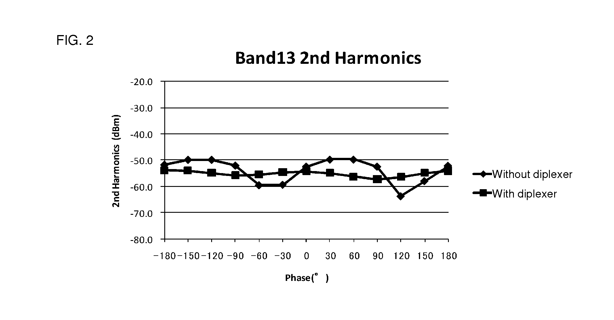
The present invention provides a high-frequency module and communication device that reduce the signal level of a harmonic transmitting from an antenna. The invention achieves this by allowing the harmonic of the transmitting signal to escape to ground via a harmonic branch circuit, while preventing the harmonic from reaching the second signal path and being received by the receiving signals. This ensures stable harmonic characteristics, even when a harmonic source or a harmonic reflector is connected as an external circuit. The invention also improves reception sensitivity for both the transmitting signals and the receiving signals. Overall, the invention ensures a stable and low signal level of harmonic transmitting from the antenna.

Problems solved by technology

In the case where a frequency band of the harmonic is used by another communication system, this may pose a problem of lowering reception sensitivity and the like of another communication system.
Thus, it is difficult to obtain sufficient attenuation of the second-order harmonic of LTE-Band 13 with a reception filter provided in a GPS receiver.

Method used


Image

  • High-frequency module and communication device
  • High-frequency module and communication device
  • High-frequency module and communication device

Examples


Embodiment Construction

[0027]First, a high-frequency module and a communication device according to a first preferred embodiment of the present invention are described.

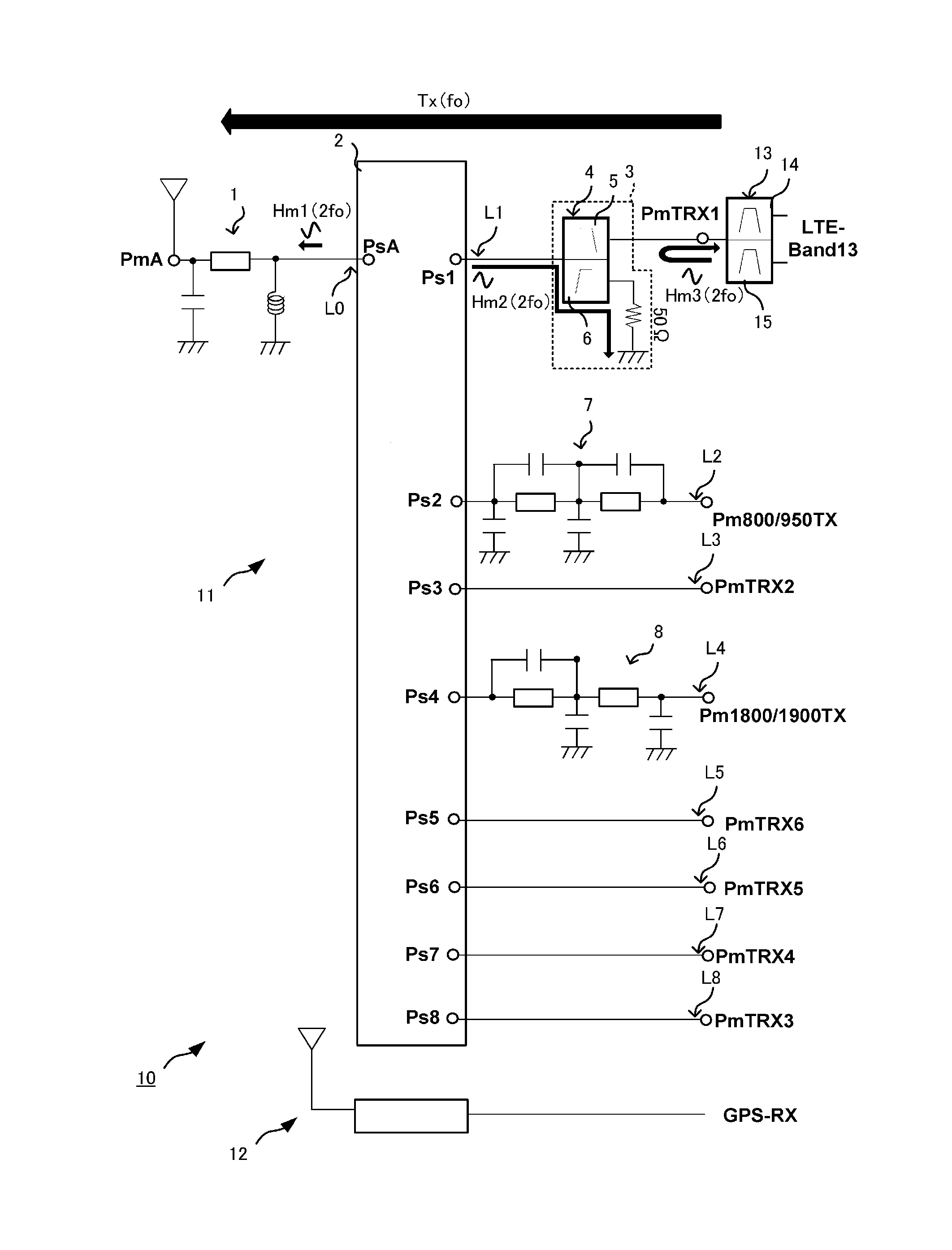
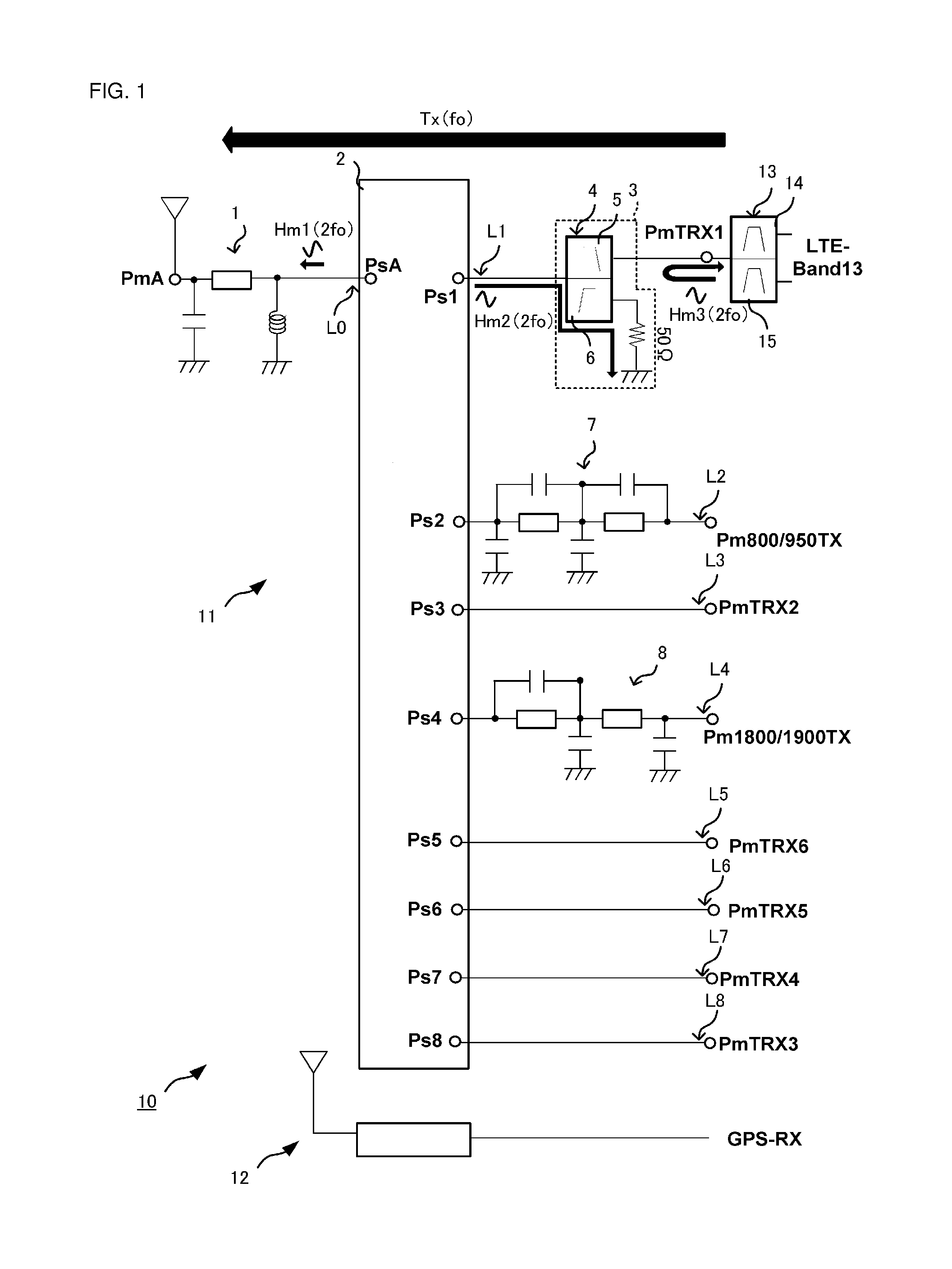
[0028]FIG. 1 is a schematic circuit diagram of a communication device according to the first preferred embodiment.

[0029]A communication device 10 depicted in FIG. 1 includes a high-frequency module 11, a GPS receiver 12, a duplexer 13, and a plurality of transceiver circuits that are not illustrated.

[0030]The communication device 10 performs wireless communications using a plurality of communication methods. The high-frequency module 11 is connected between a single antenna and a transmitter circuit or a receiver circuit in a subsequent stage, which is not illustrated. The high-frequency module 11 has the capability of transmitting and receiving transmitting signals and receiving signals corresponding to the plurality of communication methods using the single antenna as a common antenna. The GPS receiver 12 includes its own antenna and rece...


PUM


Abstract

A high-frequency module is connected to a switch port and a switch IC including an antenna connection port and a plurality of switch ports. The high-frequency module includes a signal path that outputs transmitting signals having a predetermined frequency band to the switch IC, a module port connected to the signal path and to which a duplexer and a transmitter circuit are connected, and a harmonic branch circuit that is provided on the signal path and allows a harmonic of the transmitting signal to escape to ground.

Description

BACKGROUND OF THE INVENTION[0001]1. Field of the Invention[0002]The present invention relates to high-frequency modules provided in antenna front-ends of wireless communication devices such as cellular phones and to communication devices each including a high-frequency module and a receiver that is separately provided in addition to the high-frequency module.[0003]2. Description of the Related Art[0004]FIG. 5 is a circuit diagram of a high-frequency module according to an exemplary prior art (for example, see Japanese Unexamined Patent Application Publication No. 2007-129459) to be used in an antenna front-end of a cellular phone and the like. A high-frequency module 101 includes a switch IC 102, a duplexer 103, and a duplexer 104. The high-frequency module 101 has the capability of transmitting and receiving signals in a first communication band and a second communication band using a transmission / reception antenna Ant1. The switch IC 102 includes an antenna connection port PsA1 an...

Claims


Application Information

Patent Timeline
IPC IPC(8): H04B1/52H04B1/00
CPCH04B1/0057H04B1/52H04B1/006H04B1/0064H04B1/3805H04B1/406
Inventor UEJIMA, TAKANORI
Owner MURATA MFG CO LTD
Learn More