Server chassis capable of accessing and rotating storage devices accommodated therein

a server chassis and storage device technology, applied in the server field, can solve the problems of increasing inconvenience to users, and needing to accommodate more storage devices in a very limited casing space, so as to reduce shorten the distance between the power supply port and the casing length, and minimize the effect of the space occupied by the server system

Active Publication Date: 2015-11-26
SUPER MICRO COMP
View PDF15 Cites 16 Cited by
  • Summary
  • Abstract
  • Description
  • Claims
  • Application Information

AI Technical Summary

Benefits of technology

[0008]The present invention also provides another server chassis capable of accessing and rotating the storage devices, and the input / output backplane of the rotatable rack has power supply port. The power supply port and the power supply module are disposed on the same side of the casing, thereby shortening the distance between the power supply port and the power supply module.
[0009]Compared to the conventional technique, the server chassis of the present invention includes rotatable racks axially disposed in the casing and rotatable with respect to the casing. By the rotation of the rotatable rack, the storage devices can be obliquely pulled out or inserted into the rotatable rack, thereby shortening the length of the casing, and also minimizing the space occupied by the server system. Through this arrangement, practicality and flexibility for using can be achieved.

Problems solved by technology

However, due to the demand of calculation ability and massive data storage, the server needs to accommodate more storage devices in a very limited casing space.
However, since the user needs to change or replace the storage devices in the server, the server casing needs to reserve sufficient space for replacing or accessing the storage devices.
Therefore, if the interior of the casing of the server is provided with storage devices arranged side by side, the length of the casing also needs to be elongated, which increases the space occupied by the server system and causes inconvenience to the user.

Method used


Image

  • Server chassis capable of accessing and rotating storage devices accommodated therein
  • Server chassis capable of accessing and rotating storage devices accommodated therein
  • Server chassis capable of accessing and rotating storage devices accommodated therein

Examples


Embodiment Construction

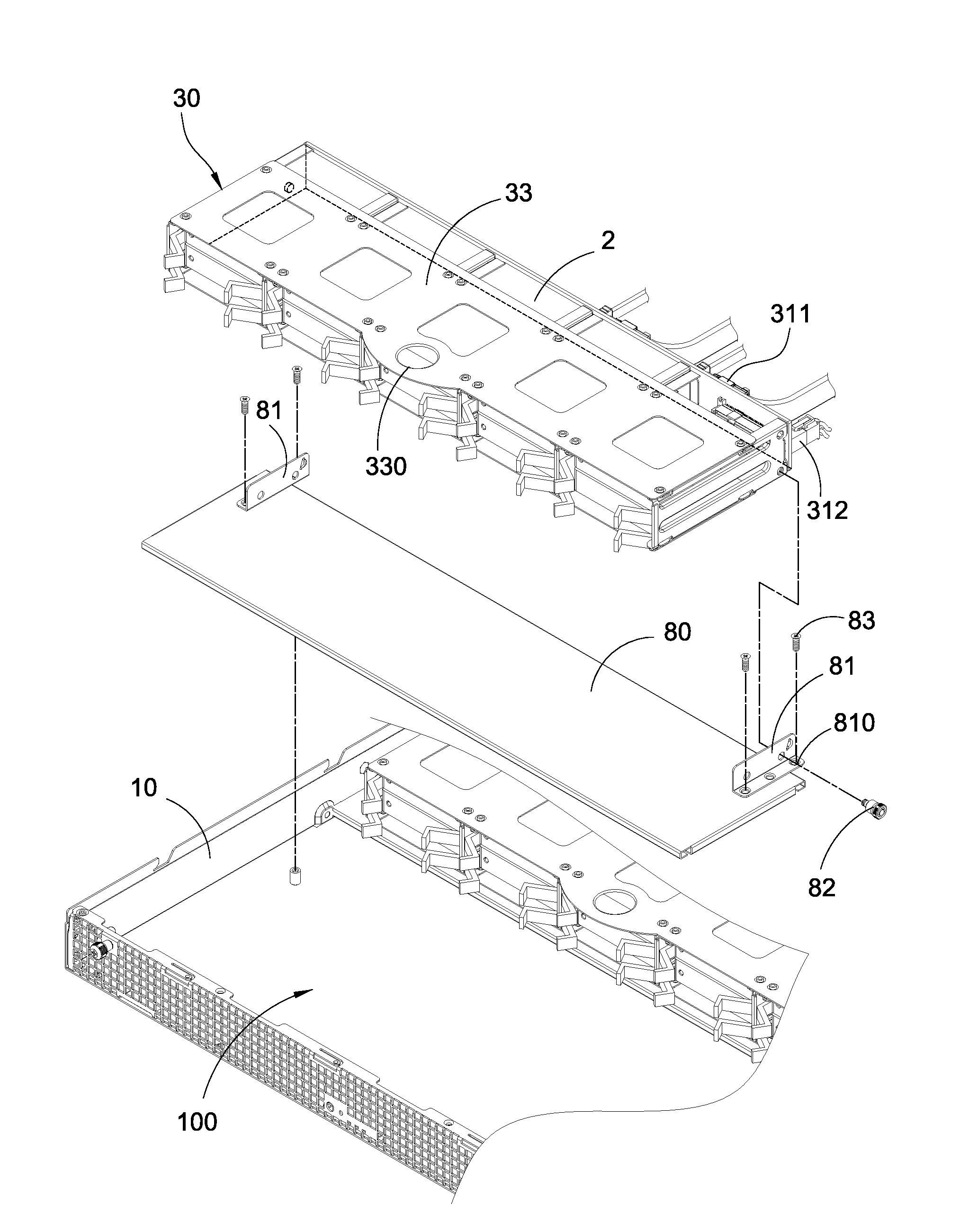
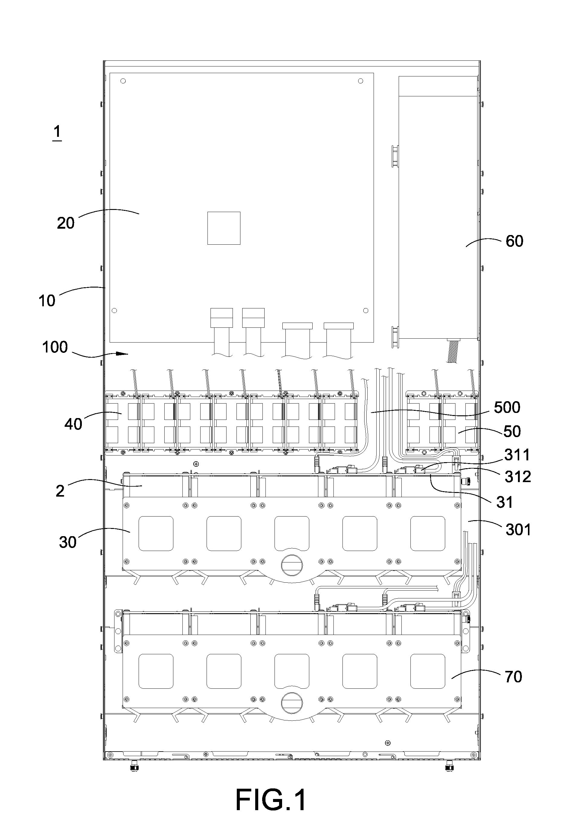
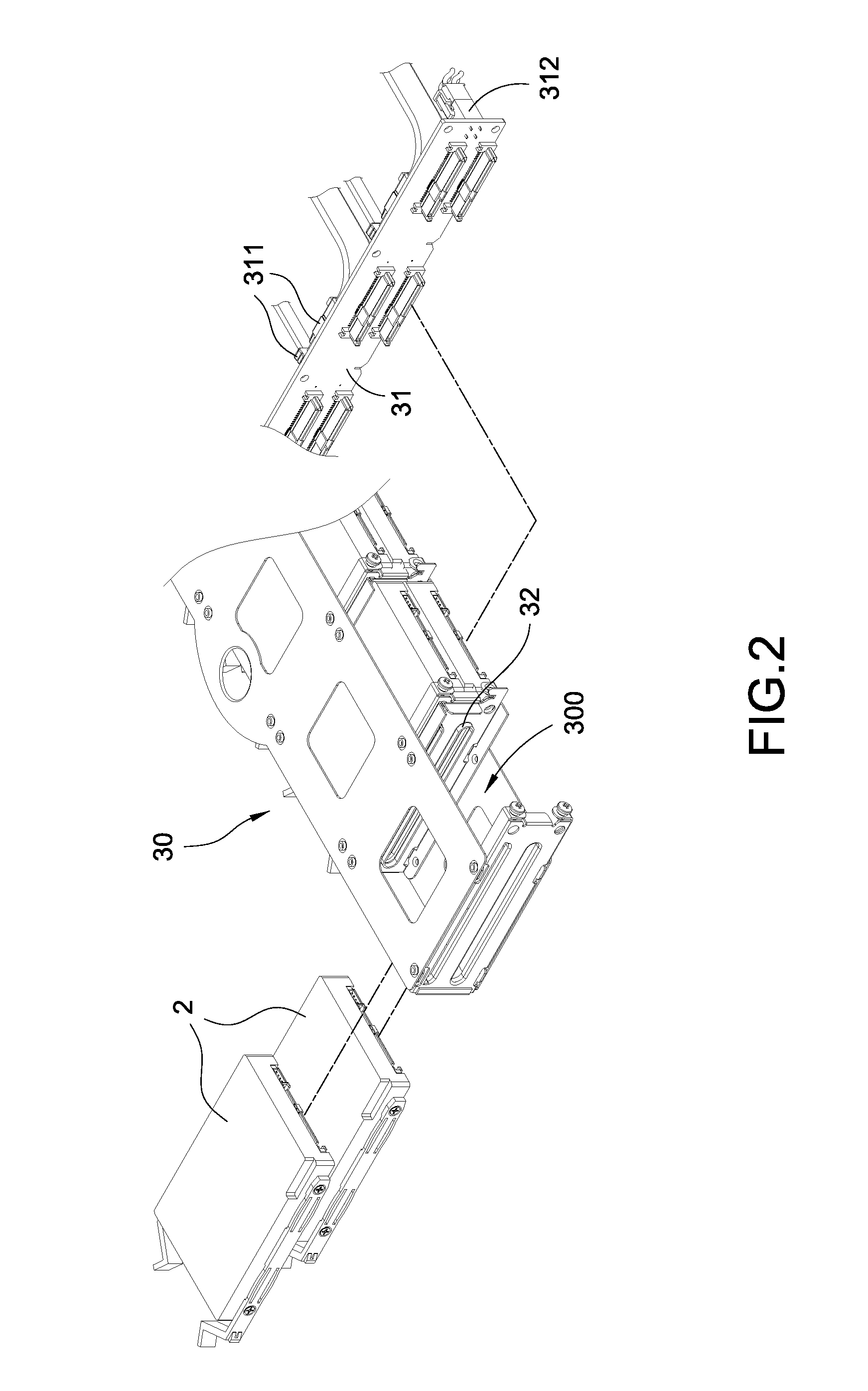
[0022]Please refer to FIG. 1. The server chassis 1 of the present invention includes a casing 10, a motherboard 20, a rotatable rack 30, a fan module 40, and an electronic device 50. The motherboard 20, the rotatable rack 30, the fan module 40, and the electronic device 50 are disposed inside the casing 10. The rotatable rack 30 is able to rotate with respect to the casing 10. In the present embodiment, the electronic device 50 is replaced with another fan module.

[0023]The casing 10 includes an accommodating space 100, and the motherboard 20 is disposed in the accommodating space 100. The rotatable rack 30 is axially disposed in the accommodating space 100 and able to rotate with respect to the casing 10. The fan module 40 is disposed in the accommodating space 100 and electrically connected to the motherboard 20. In the present embodiment, the fan module 40 is disposed on one side of the rotatable rack 30 (back of the rotatable rack 30, near mother board 20). Additionally, the elec...


PUM


Abstract

A server chassis includes a casing, a motherboard, a rotatable rack and an electronic device. The rotatable rack is axially disposed inside the casing and able to rotate with respect to the casing. The rotatable rack has a plurality of insertion spaces. The electronic device is provided on one side of the rotatable rack, and a cord passage is provided between the fan module and the electronic device. The storage devices accommodated in the rotatable rack is electrically connected to the motherboard via the cord passage, thereby increasing the quantity of the storage devices and decreasing the length of the casing.

Description

BACKGROUND[0001]1. Technical Field[0002]The present invention relates to a server, particularly to a server chassis capable of accessing and rotating storage devices accommodated therein.[0003]2. Related Art[0004]The conventional server system mainly has electronic components such as the motherboard, the storage devices, or the power supply installed in the casing, and the interior space of the casing is usually divided into a plurality of insertion spaces which are provided to accommodate multiple storage devices arranged in an array. The most common storage device includes a hard disk drive or a solid state drive, etc. However, due to the demand of calculation ability and massive data storage, the server needs to accommodate more storage devices in a very limited casing space. Therefore, the size of the server casing also needs to be change correspondingly.[0005]However, since the user needs to change or replace the storage devices in the server, the server casing needs to reserve...

Claims


Application Information

Patent Timeline
Patent Type & Authority Applications(United States)
IPC IPC(8): H05K7/14H05K7/20
CPCH05K7/1489H05K7/20736H05K7/1492H05K7/1491H05K7/1487G11B33/128
Inventor CHEN, RICHARD S.WU, CHAOCHING
Owner SUPER MICRO COMP
Why Eureka
Try Eureka