Electrohydraulic Motor Vehicle Brake System and Method for Operating the Same

a technology of electric hydrodynamic brakes and motor vehicles, applied in braking systems, computations using non-denominational number representations, analog and hybrid computing, etc., can solve problems such as unsatisfactory pressure compensation, and achieve the effect of advantageous functionality

Active Publication Date: 2015-12-03
LUCAS AUTOMOTIVE GMBH
View PDF7 Cites 27 Cited by
  • Summary
  • Abstract
  • Description
  • Claims
  • Application Information

AI Technical Summary

Benefits of technology

[0009]The aim is to provide an electrohydraulic motor-vehicle brake system and a method for operating

Problems solved by technology

However, the minimisation to only one valve for each wheel brake also creates challen

Method used


Image

  • Electrohydraulic Motor Vehicle Brake System and Method for Operating the Same
  • Electrohydraulic Motor Vehicle Brake System and Method for Operating the Same
  • Electrohydraulic Motor Vehicle Brake System and Method for Operating the Same

Examples


Embodiment Construction

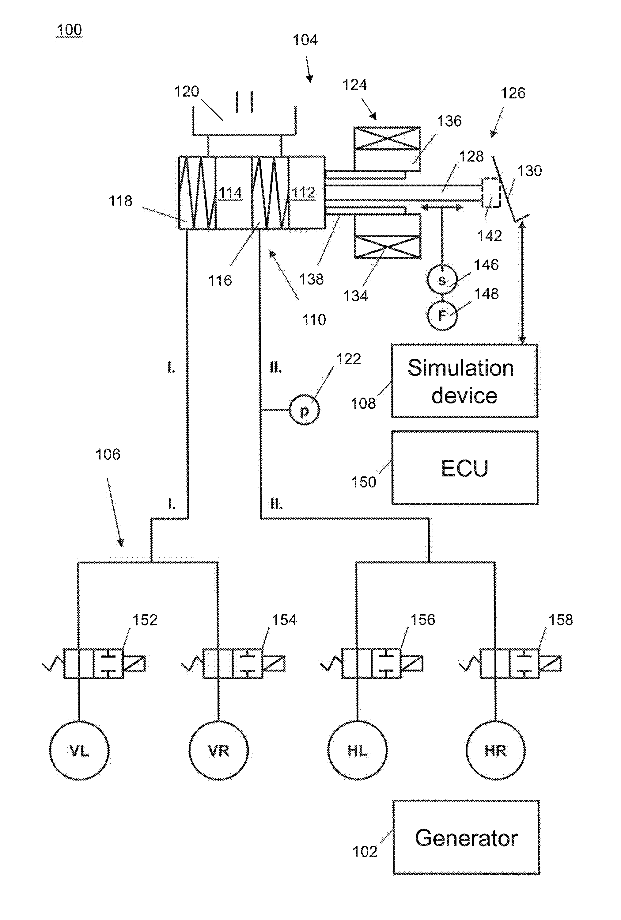
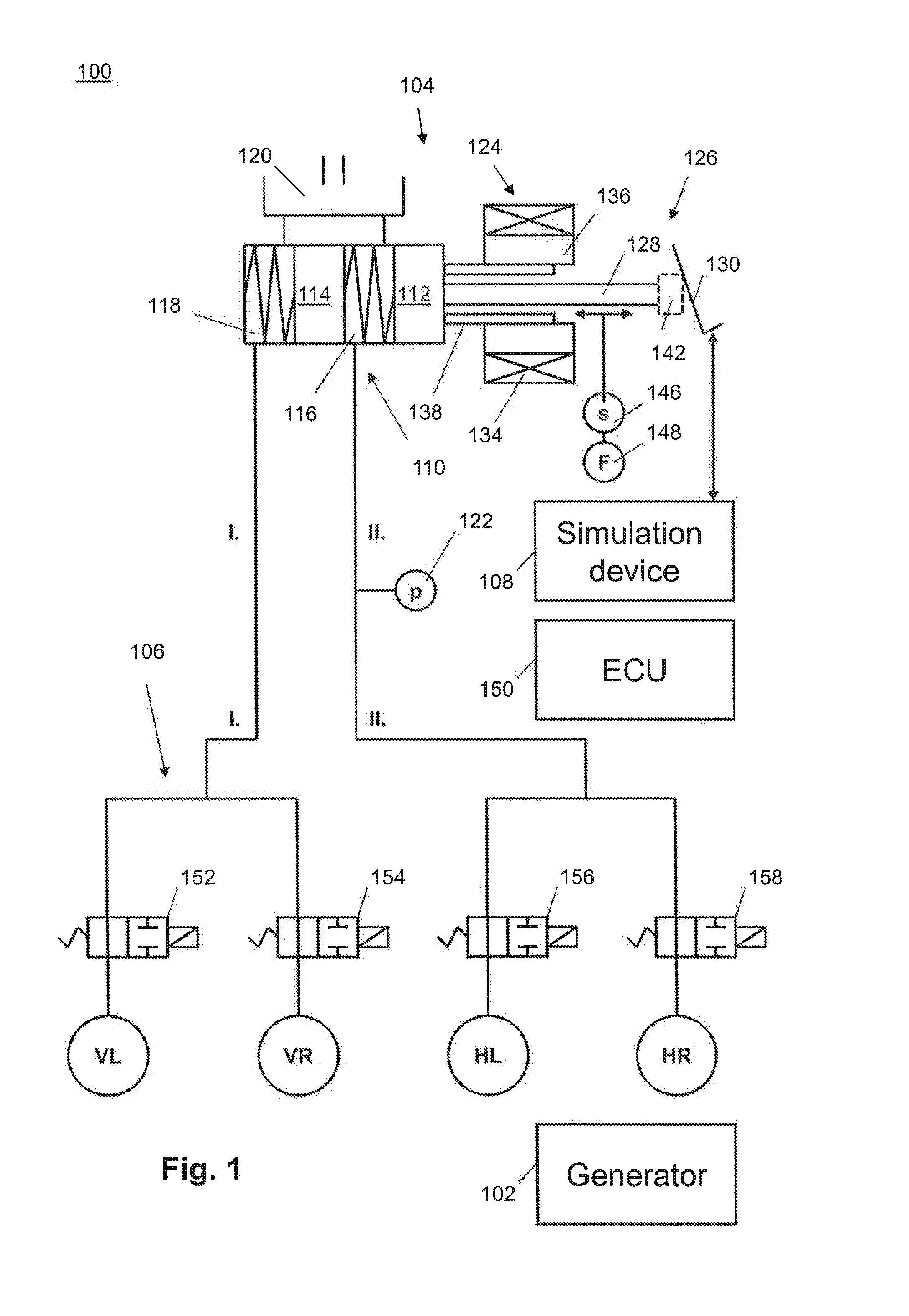
[0040]FIG. 1 shows a first exemplary embodiment of a hydraulic vehicle brake system 100 which is based on the brake-by-wire (BBW) principle. The brake system 100 can be optionally operated in regenerative mode (e.g. in the case of hybrid vehicles). To this end, an electric machine 102 is provided, which offers a generator functionality and can be selectively connected to wheels and an energy store, e.g. a battery (not shown).

[0041]As shown in FIG. 1, the brake system 100 comprises a master cylinder assembly 104, which can be mounted on a vehicle splashboard. A hydraulic control unit (HCU) 106 of the brake system 100 is functionally arranged between the master cylinder assembly 104 and four wheel brakes VL, VR, HL and HR of the vehicle. The HCU 106 is constructed as an integrated assembly and comprises a plurality of hydraulic individual components as well as a plurality of fluid inlets and fluid outlets. A simulation device 108 (only shown schematically) for providing a pedal reacti...


PUM


Abstract

The invention relates to a technique for operating an electrohydraulic motor vehicle brake system comprising a master cylinder, an electromechanical actuator for generating a hydraulic pressure at a plurality of wheel brakes and a set of electrically actuable valve arrangements. The set of valve arrangements comprises a first valve arrangement between the master cylinder and every wheel brake. The first valve arrangements can be controlled in the multiplex operation to generate, by means of the electromechanical actuator, the respective brake pressure intended for each of the wheel brakes. According to an aspect of this technique, the method comprises the steps of: generating a feedback current during the multiplex operation by operating an electric motor of the electromechanical actuator as a generator and supplying the feedback current to at least one electrical load.

Description

CROSS-REFERENCE TO RELATED APPLICATIONS[0001]This application is a national stage of International Application No. PCT / EP2013 / 074922 filed Nov. 28, 2013, and which claims priority to German Patent Application No. 10 2012 025 423.7 filed Dec. 21, 2012, the disclosures of which are incorporated herein by reference in their entirety.BACKGROUND OF THE INVENTION[0002]The present disclosure relates in general to the field of vehicle brake systems. In concrete terms, an electrohydraulic vehicle brake system with an electromechanical actuator for actuating the brake system is described.[0003]Electromechanical actuators have already been used for some time in vehicle brake systems, for example to realise an electric parking brake function (EPB). In the case of electromechanical brake systems (EMB), they replace the conventional hydraulic cylinders on the wheel brakes.[0004]Technical advancements have resulted in a continuous increase in the capacity of the electromechanical actuators. The us...

Claims


Application Information

Patent Timeline
IPC IPC(8): B60T13/68B60T7/04B60T13/74
CPCB60T13/686B60T7/042B60T13/745B60T8/4077B60T8/4081B60T8/447B60T13/662B60T2270/604B60T2270/82
Inventor KNECHTGES, JOSEFGRIESER-SCHMITZ, STEFAN
Owner LUCAS AUTOMOTIVE GMBH
Why Eureka
Try Eureka