Constant tensioning means for rotary motion transfer apparatus

Inactive Publication Date: 2015-12-03
LAVERDA
View PDF21 Cites 9 Cited by
  • Summary
  • Abstract
  • Description
  • Claims
  • Application Information

AI Technical Summary

Benefits of technology

[0009]It is therefore an object of the invention to provide an improved rotary motion transfer apparatus wherein a shaft

Problems solved by technology

However, despite the maturity of the technology, belts and chains alike suffer from wear and tend to stretch throughout their operational life.
Although not discussed in GB-1,228,283, the tensioning of clean grain elevators is cumbersome in known combine harvesters.
The provision of additional idler sprockets in the linear elevator housing is not practical and so tensioning is typically done through longitudinal adjustment of one of the two sprockets around which

Method used


Image

  • Constant tensioning means for rotary motion transfer apparatus
  • Constant tensioning means for rotary motion transfer apparatus
  • Constant tensioning means for rotary motion transfer apparatus

Examples


Embodiment Construction

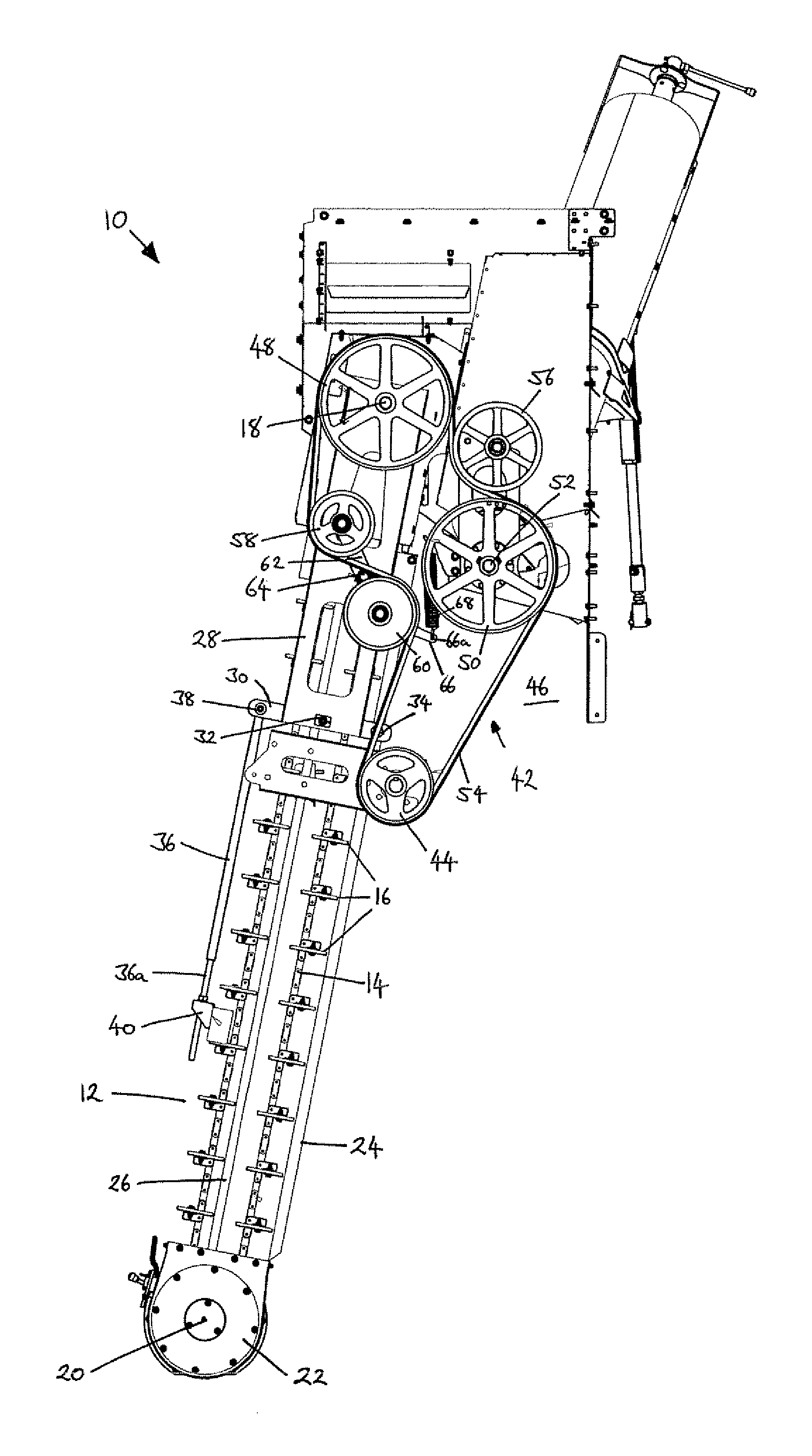
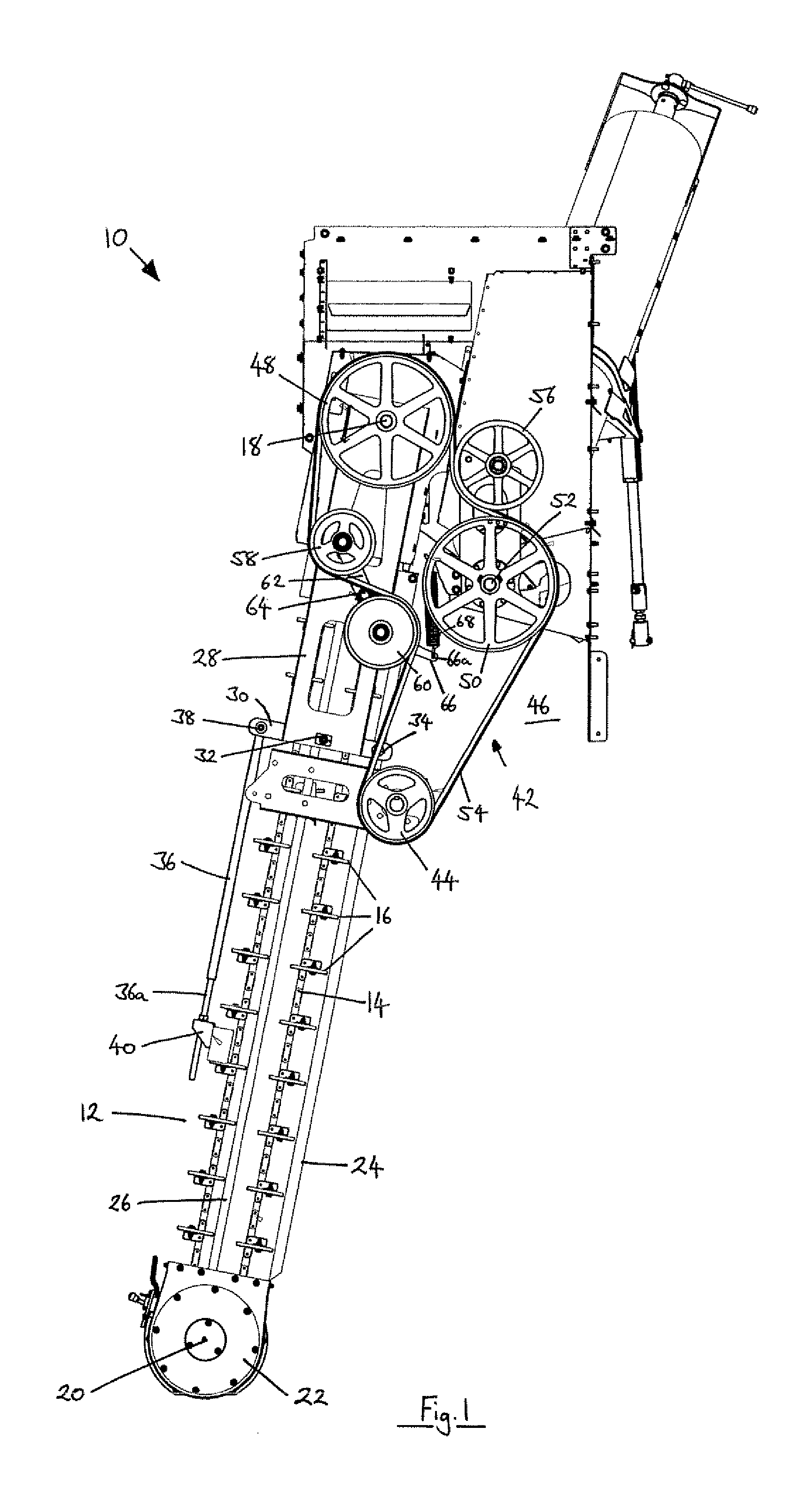
[0023]With reference to FIG. 1, a clean grain elevator system 10 is shown. It should be appreciated that part of the elevator housing has been omitted from FIG. 1 to illustrate the inner workings. The elevator system 10 forms part of a larger grain conveyance system of a combine harvester which will not be described in any detail. A transverse clean grain auger (not shown and aligned perpendicular to the plane of the drawing) delivers clean grain separated from a crop stream to the bottom of upright elevator 12.

[0024]An endless chain 14, which includes conveyance paddles 16 at regular intervals along the length thereof, is trained around upper and lower sprockets (not shown) which rotate on an upper shaft 18 and a lower shaft 20 respectively. The clean grain auger rotates on the same axis 20 as the lower sprocket. The clean grain is delivered into a lower housing 22 where it is engaged by the paddles 16 for upward conveyance.

[0025]The chain 14 resides in a tubular housing 24 of subs...


PUM


Abstract

A rotary motion transfer apparatus, such as a combine grain elevator, which includes first and second endless flexible members which may include belts and/or chains. Each flexible member is trained around a respective set of rotary members which may be pulleys, sheaves or sprockets. One rotary member from each set shares a common shaft and may, or may not, be in driving engagement with one another. The common shaft is mounted on an adjustment frame member that is linearly displaceable with respect to a main frame to adjust the tension in the first endless flexible member. A pair of idler rotary members are provided for tensioning the second endless flexible member and are mounted on a pivot arm which is mounted to the adjustment frame member for pivoting movement around a pivot axis intermediate the pair of idler rotary members. A lever is secured to the pivot arm, and spring means are attached between the lever and the main frame to bias the idler rotary members into engagement with opposite sides of the second endless flexible member with a substantially constant force over an adjustment range of the common shaft.

Description

FIELD OF INVENTION[0001]The invention relates to rotary transfer apparatus comprising endless flexible members including belts and chains. In particular, the invention relates to the tensioning of such endless flexible members to accommodate wear and geometric changes upon adjustment actions.BACKGROUND[0002]The use of belts and chains to transfer rotary motion in mechanical drive systems is well known. However, despite the maturity of the technology, belts and chains alike suffer from wear and tend to stretch throughout their operational life. To maintain a desired tension in the belts or chains, various known tensioning mechanisms exist today.[0003]In one approach, the position of the sprockets, pulleys of sheaves can be adjusted to change the geometry of the chain or belt's path. Adjustable idler sprockets or pulleys can be included in the path of the chain or belt to adjust the effective length and thus the tension. Idler wheels can be mounted in a spring-loaded manner so as to c...

Claims


Application Information

Patent Timeline
IPC IPC(8): B65G23/44A01F12/46F16H7/12B65G23/24
CPCB65G23/44B65G23/24F16H2007/0808F16H7/12A01F12/46F16H7/1281F16H2007/0893
Inventor HOLLATZ, BRIAN JAY
Owner LAVERDA
Why Eureka
Try Eureka