Intake Valve Closure Control for Dual-Fuel Engines

a technology of intake valve and dual-fuel engine, which is applied in the direction of non-mechanical valves, machines/engines, mechanical apparatus, etc., can solve the problems of compression ignition, lng can detonate and damage the engine, and not work well

Active Publication Date: 2015-12-03
CATERPILLAR INC
View PDF5 Cites 6 Cited by
  • Summary
  • Abstract
  • Description
  • Claims
  • Application Information

AI Technical Summary

Benefits of technology

[0010]In one aspect, an actuation system for an intake valve of an internal combustion engine is disclosed. The system may include a hydraulic circuit that may include a master cylinder, a control valve, an accumulator, a first one-way valve and a slave cylinder. The slave cylinder may accommodate a slave piston and the slave piston may be coupled to the intake valve. The control valve may be disposed upstream of the accumulator for controlling flow from the hydraulic circuit to the accumulator. The first one-way valve may be disposed downstream of the accumulator for permitting flow from the accumulator to the hydraulic circuit and for preventing flow from the hydraulic circuit to the accumulator without passing through the control valve. Further, the control valve may have an open position providing communication between the hydraulic circuit and the accumulator and a closed position for preventing communication between the hydraulic circuit and the accumulator. Optionally, a second one-way valve may be disposed upstream of the hydraulic circuit allowing flow from the fluid supply to the hydraulic circuit and preventing flow back to the fluid supply.

Problems solved by technology

Compression ignition, as the process is called, does not work well with LNG alone because it is too difficult to control exactly when combustion occurs.
As a result, the LNG can detonate and damage the engine.
While a high compression ratio is desired for diesel, use of an Otto cycle and a high compression ratio with LNG may result in knocking.

Method used


Image

  • Intake Valve Closure Control for Dual-Fuel Engines
  • Intake Valve Closure Control for Dual-Fuel Engines
  • Intake Valve Closure Control for Dual-Fuel Engines

Examples


Embodiment Construction

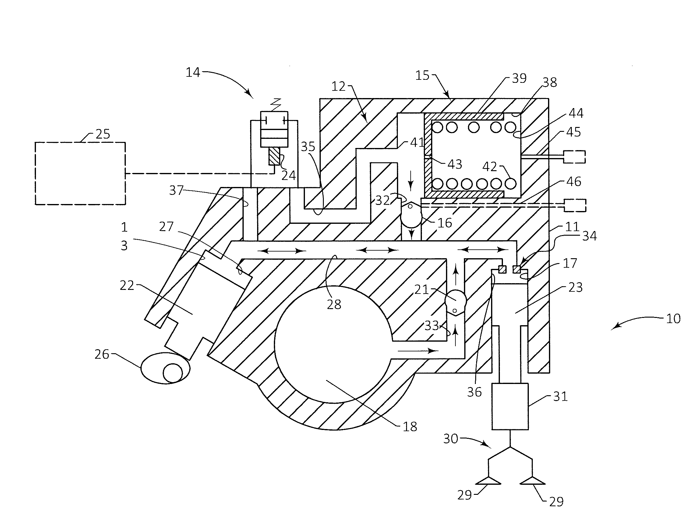
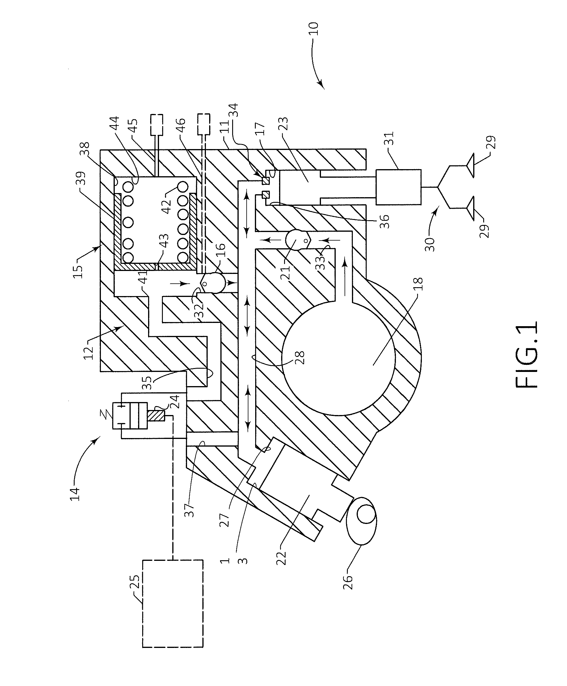
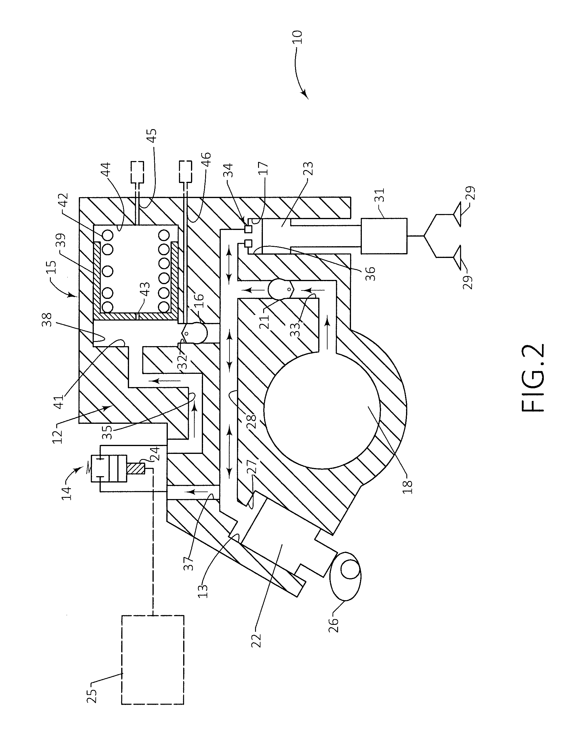
[0024]FIG. 1 illustrates part of an engine 10 that may include a block 11 or other suitable structure for accommodating the hydraulic circuit 12. The hydraulic circuit 12 may include a master cylinder 13, a control valve 14, an accumulator 15, a first one-way valve 16, a slave cylinder 17, and a fluid supply 18 and a second one-way valve 21. The master cylinder 13 may accommodate a master piston 22. The term master cylinder 13 is intended to cover a cylindrical receiving space for the master piston 22. The master cylinder 13 may be provided in the form of a bore, as shown in FIGS. 1-2, or the master cylinder 13 may be a separate component (not shown). Similarly, the slave cylinder 17 may accommodate a slave piston 23. The slave cylinder 17 may be in the form of a bore, as shown in FIGS. 1-2, or it may be a separate component as illustrated in FIGS. 3-6 and described below.

[0025]Returning to FIG. 1, the operation of the hydraulic circuit 12 with the control valve 14 in its normally c...


PUM


Abstract

A system and a method for actuating intake valves of an internal combustion engine. The system includes a hydraulic circuit including a master cylinder, a control valve, an accumulator, a first one-way valve and a slave cylinder. The slave cylinder accommodates a slave piston, which is coupled to the intake valves. The control valve is disposed upstream of the accumulator for controlling flow from the hydraulic circuit to the accumulator. The first one-way valve is disposed downstream of the accumulator for permitting flow from the accumulator to the hydraulic circuit and for preventing flow from the hydraulic circuit to the accumulator without first passing through the control valve. The control valve has an open position that provides communication between the hydraulic circuit and the accumulator for a Miller cycle or Miller-like cycle operation. The control valve also has a closed position that prevents communication between the hydraulic circuit and the accumulator during Otto cycle operation.

Description

BACKGROUND[0001]1. Technical Field[0002]Disclosed herein are methods and apparatuses for controlling the opening and closing of combustion cylinder intake valves of dual-fuel internal combustion engines.[0003]2. Description of the Related Art[0004]Technology that allows diesel engines to run primarily on liquefied natural gas (LNG) may provide an economical way to shift fuel consumption from diesel to LNG. Such a shift could lower greenhouse gas emissions, because burning LNG emits less carbon dioxide per unit of energy than diesel. Shifting from diesel to LNG may save costs, because LNG is cheaper per unit of energy than diesel. Dual-fuel engines, which burn both diesel and LNG, are advantageous because an operator can revert to diesel if LNG is not available or if the price of natural gas rises.[0005]Diesel engines may be converted to run primarily on LNG with relatively small modifications. In a diesel engine, the air-fuel mixture is not ignited with a spark, as in gasoline engin...

Claims


Application Information

Patent Timeline
Patent Type & Authority Applications(United States)
IPC IPC(8): F01L9/02F01L1/34F01L1/24F01L9/10
CPCF01L9/02F01L1/34F01L1/24Y02T10/12F01L9/10
Inventor YEAGER, KENDALL D.SCHREADER, KEVIN J.YACOUB, VICTOR I.LANGEWISCH, EDWIN HENRY
Owner CATERPILLAR INC
Why Eureka
Try Eureka