Hybrid emergency power unit system

a power unit and hybrid technology, applied in the field of electric power generation, can solve the problems of ram air turbines being damaged during deployment into the slipstream of aircraft, adding unnecessary weight and complexity to spool generators, and affecting the operation of existing emergency power units

Active Publication Date: 2015-12-03
HAMILTON SUNDSTRAND CORP
View PDF9 Cites 19 Cited by
  • Summary
  • Abstract
  • Description
  • Claims
  • Application Information

AI Technical Summary

Benefits of technology

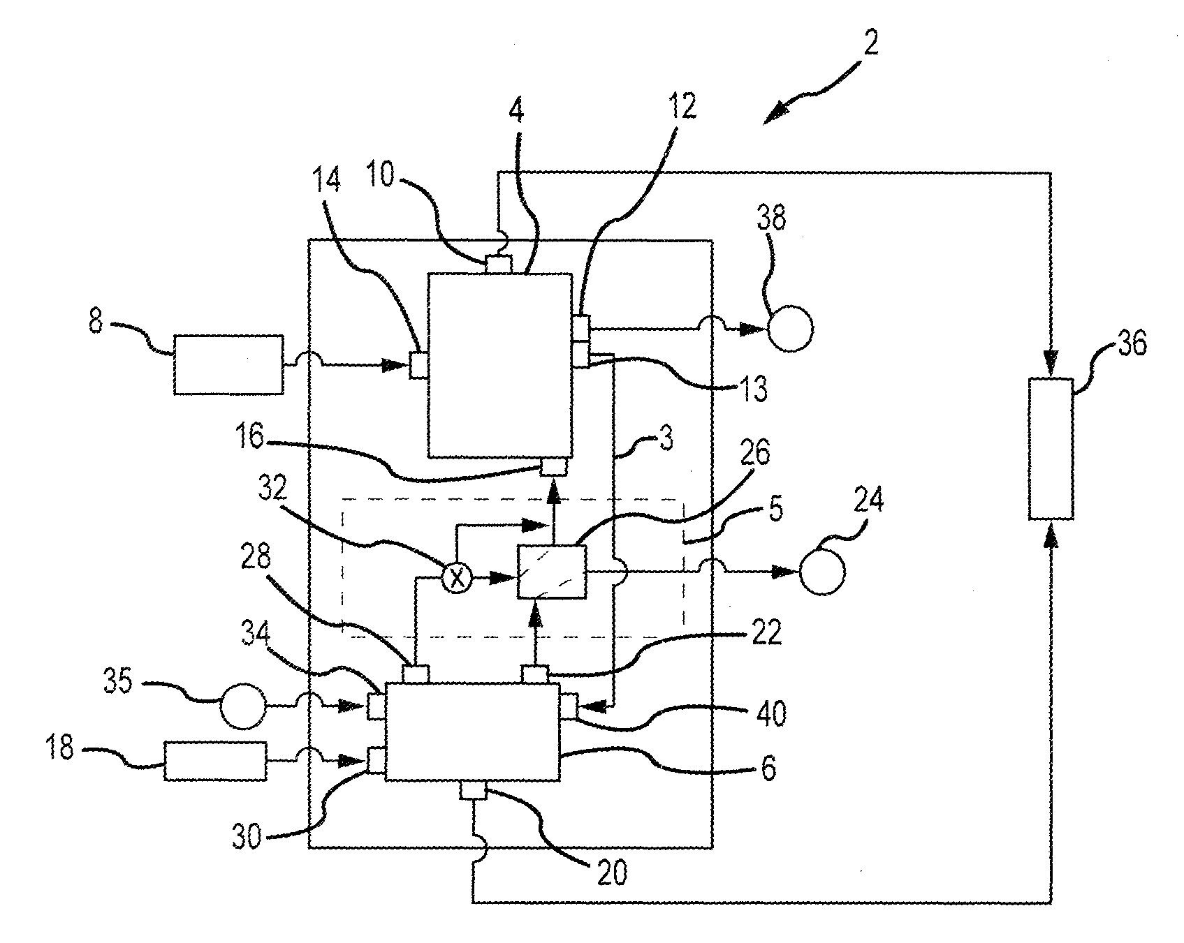
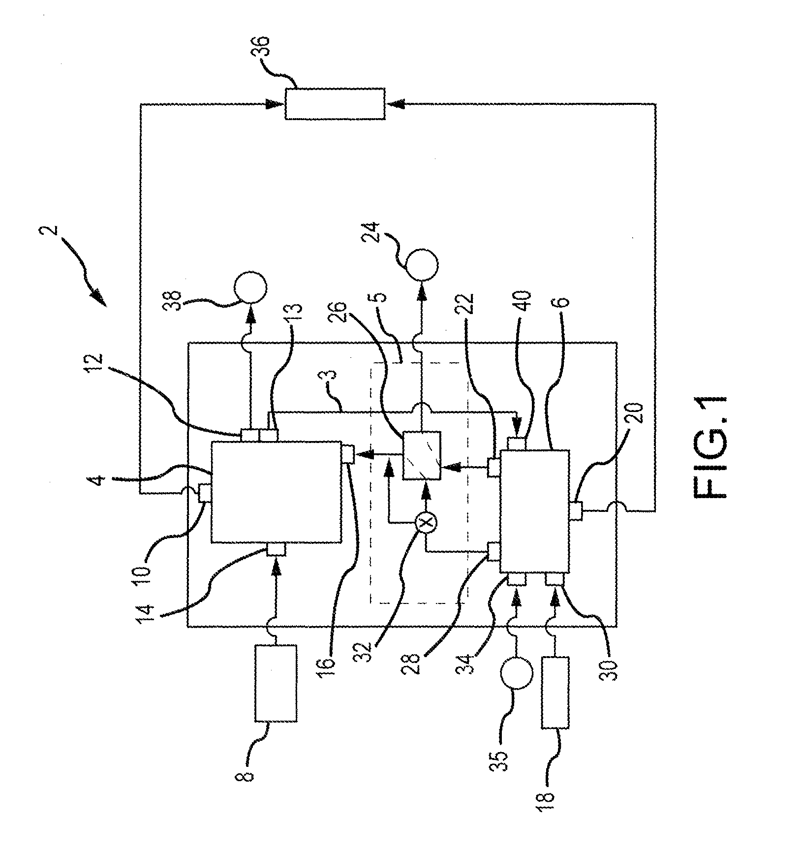
[0004]An energy conversion system may have an integrated emergency power unit, an auxiliary power unit (APU), and an emergency power unit efficiency improvement apparatus. The emergency power unit may have a fuel cell. The auxiliary power unit may have an engine and a generator wherein the engine drives the generator to produce electrical power. The emergency power unit efficiency improvement apparatus may have a heat exchanger and a bypass valve. The heat exchanger may be in fluidic communication with the emergency power unit and the auxiliary power unit.
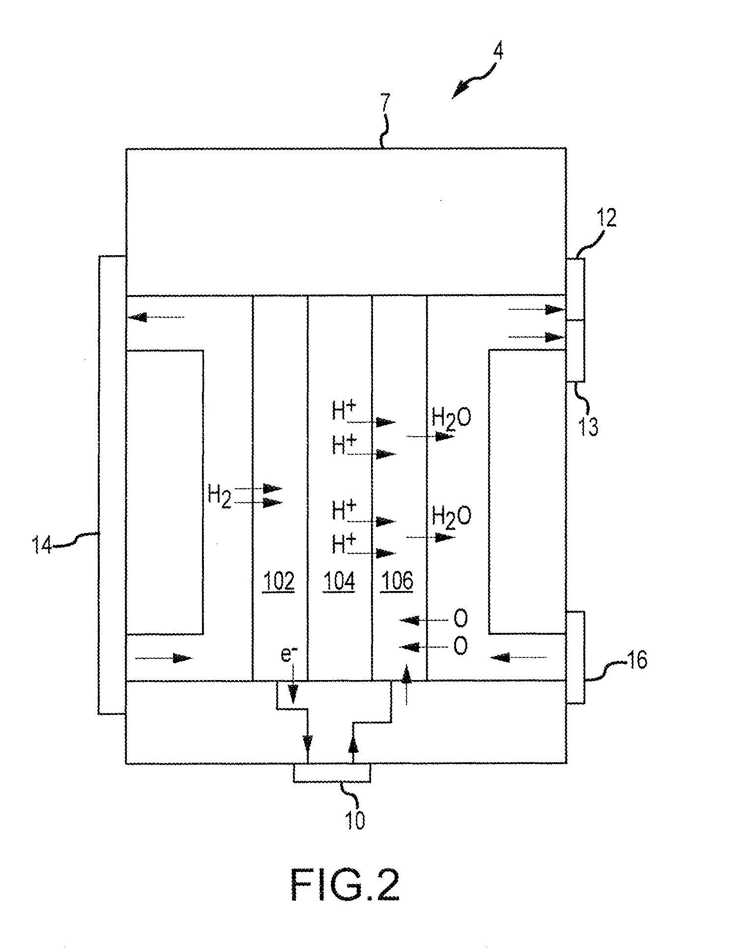
[0005]In some embodiments, an energy conversion system may have an emergency power unit having a fuel cell, and an emergency power unit efficiency improvement apparatus having a heat exchanger and a bypass valve. The heat exchanger may be in fluidic communication with the emergency power unit. The heat exchanger may heat compressed air which is supplied to the inlet / air intake of the emergency power unit.

Problems solved by technology

However, existing emergency power units encounter operational challenges.
For example, ram air turbines can be damaged during deployment into the aircraft's slipstream.
Also, compressor bleed air driven systems are inoperable if the main engine fails unless there is a low-pressure spool generator operating during wind milling of the main engine fan(s), though this spool generator adds unwanted weight and complexity.
Moreover, solid propellant-based power systems are unstable and prone to contamination and aging, and extant fuel cell based emergency power units require near-atmospheric inlet air pressure and relatively high inlet temperatures.

Method used


Image

  • Hybrid emergency power unit system
  • Hybrid emergency power unit system
  • Hybrid emergency power unit system

Examples


Embodiment Construction

[0010]The following description is of various exemplary embodiments only, and is not intended to limit the scope, applicability or configuration of the present disclosure in any way. Rather, the following description is intended to provide a convenient illustration for implementing various embodiments including the best mode. As will become apparent, various changes may be made in the function and arrangement of the elements described in these embodiments without departing from the scope of the appended claims.

[0011]For the sake of brevity, conventional techniques for manufacturing and construction may not be described in detail herein. Furthermore, the connecting lines shown in various figures contained herein are intended to represent exemplary functional relationships and / or physical couplings between various elements. It should be noted that many alternative or additional functional relationships or physical connections may be present in a practical method of construction.

[0012]...


PUM

PropertyMeasurementUnit
electrical poweraaaaaaaaaa

Abstract

An integrated hybrid emergency power system having various features is disclosed. A hybrid emergency power system may have an auxiliary power unit and an emergency power unit. The emergency power unit may have a fuel cell. The auxiliary power unit may have an engine. The emergency power unit may be connected to the auxiliary power unit by an emergency power unit efficiency improvement apparatus. In this manner, the operating efficiency of the emergency power unit may be enhanced.

Description

FIELD[0001]The present invention relates to the field of electrical power generation. More particularly, the present disclosure relates to an airborne emergency electrical power system capable of operating in the event of an aircraft engine failure.BACKGROUND[0002]Airplanes have utilized various emergency power units (“EPUs”) to provide electrical power in the event of an engine failure. However, existing emergency power units encounter operational challenges. For example, ram air turbines can be damaged during deployment into the aircraft's slipstream. Also, compressor bleed air driven systems are inoperable if the main engine fails unless there is a low-pressure spool generator operating during wind milling of the main engine fan(s), though this spool generator adds unwanted weight and complexity. Moreover, solid propellant-based power systems are unstable and prone to contamination and aging, and extant fuel cell based emergency power units require near-atmospheric inlet air pres...

Claims


Application Information

Patent Timeline
Patent Type & Authority Applications(United States)
IPC IPC(8): H01M8/04H02K7/18B64D41/00H02J9/06
CPCH01M8/04067H02J9/066H02K7/1823B64D2041/005H01M8/04201B64D41/00H01M2250/20H01M8/04156H01M2250/407H02J4/00H02J2310/44Y02B90/10Y02E60/50Y02T90/40
Inventor RIBAROV, LUBOMIR A.VEILLEUX, JR., LEO J.
Owner HAMILTON SUNDSTRAND CORP
Why Eureka
Try Eureka