Fuel cell system and control method for the same

a fuel cell and control method technology, applied in the field of fuel cell systems and control methods, can solve problems such as discomfort, and achieve the effect of reducing the degree of wetness of fuel cells

Active Publication Date: 2015-12-03
NISSAN MOTOR CO LTD
View PDF0 Cites 5 Cited by
  • Summary
  • Abstract
  • Description
  • Claims
  • Application Information

AI Technical Summary

Benefits of technology

[0004]The present invention was developed in view of such a problem. An object of the present invention is to provide a fuel cell system capable of reducing a degree of wetness of a fuel cell without causing a sense of discomfort to a passenger.

Problems solved by technology

Further, in regulating the rotation speed of the air compressor, operation noise of the air compressor varies, which may be on the ears of a passenger to cause a sense of discomfort.

Method used


Image

  • Fuel cell system and control method for the same
  • Fuel cell system and control method for the same
  • Fuel cell system and control method for the same

Examples


first embodiment

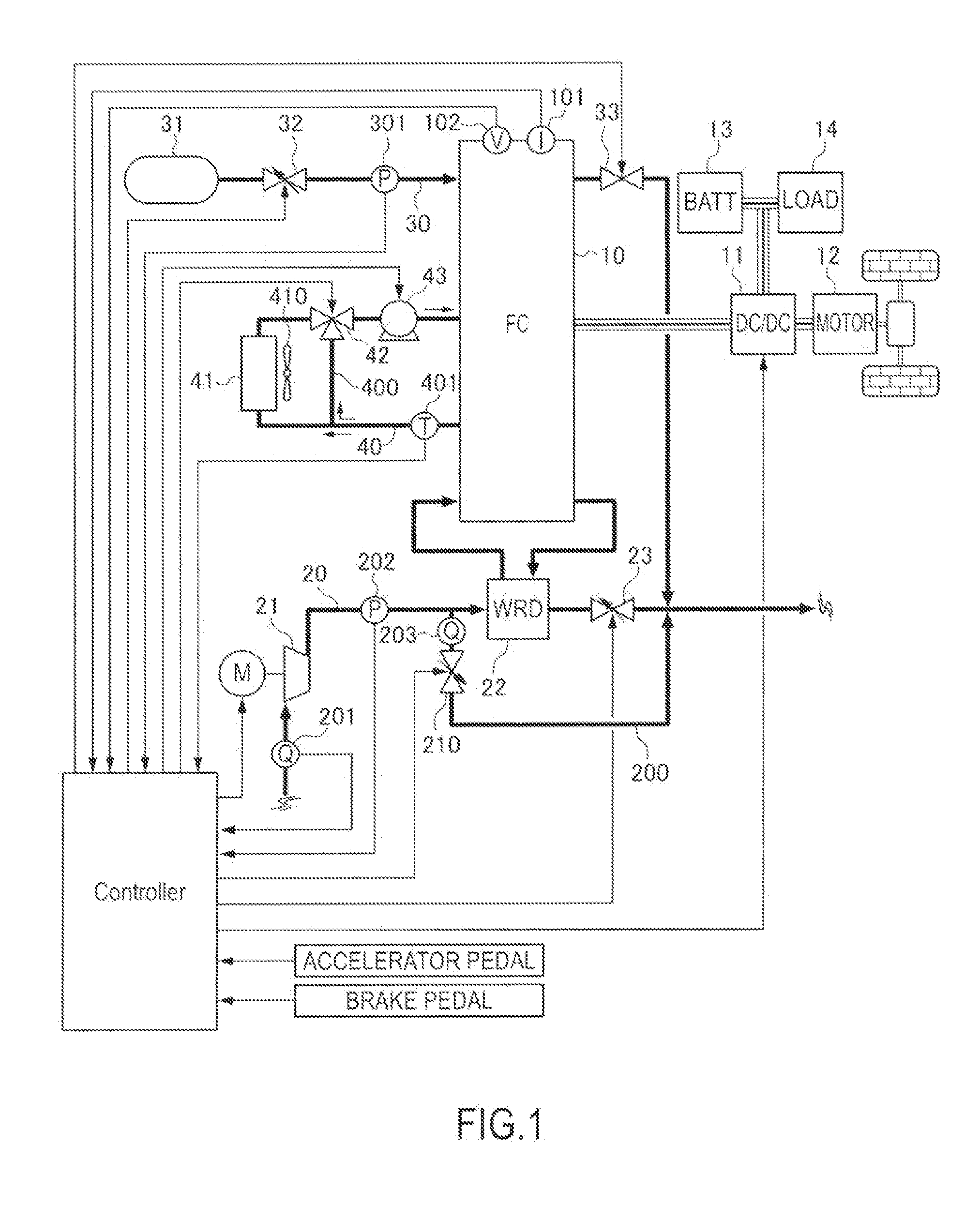
[0017]FIG. 1 is a diagram showing a basic configuration of a fuel cell system according to the present invention.

[0018]First, with reference to FIG. 1, the basic configuration of the fuel cell system according to the present invention is described.

[0019]A fuel cell stack 10 generates power by having reaction gas (cathode gas O2, anode gas H2) supplied while an electrolyte membrane is maintained in a suitable wet state. To do so, a cathode line 20, an anode line 30 and a cooling water circulation line 40 are connected to the fuel cell stack 10. It should be noted that a power generation current of the fuel cell stack 10 is detected by a current sensor 101. A power generation voltage of the fuel cell stack 10 is detected by a voltage sensor 103.

[0020]The cathode gas O2 to be supplied to the fuel, cell stack 10 flows in the cathode line 20. A compressor 21, a WRD (Water Recovery Device) 22 and a cathode pressure regulating valve 23 are provided in the cathode line 20. Further, a bleed ...

second embodiment

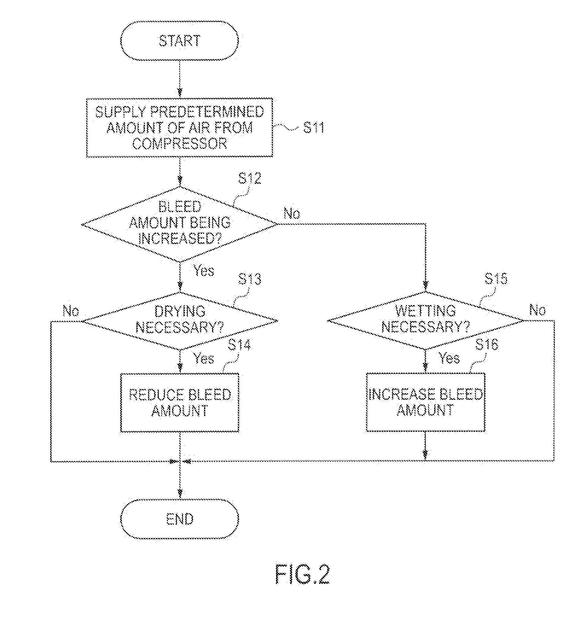
[0061]FIG. 6 is a control flow chart executed by a controller of a fuel cell system according to a second embodiment. It should be noted that components fulfilling functions similar to the aforementioned ones are denoted by the same reference signs and repeated description is omitted as appropriate below.

[0062]In the present embodiment, a control is executed, during an operation in which bleeding is performed (i.e. during an operation in which the opening of the bleed valve is not zero). Specifically, the controller determines whether or not the operation in which bleeding is performed is in execution in Step S21, and shifts a process to Step S12 if the determination result is affirmative while shifting the process to Step S15 if the determination result is negative. If wetting is necessary, the bleed amount can be increased even if bleeding is not currently performed. Thus, such a processing is performed.

[0063]It should be noted that operation scenes in which bleeding is performed ...

third embodiment

[0065]FIG. 7 is a control flow chart executed by a controller of a fuel cell system according to a third embodiment.

[0066]Even if the bleed amount is reduced and the flow-in amount to the fuel cell stack is increased to reduce the degree of wetness of the fuel cell stack 10 (to dry the fuel cell stack 10), that effect is reduced if the cathode pressure increases. Specifically, this is because a higher cathode pressure rather functions to increase the degree of wetness. Accordingly, in the present invention, the opening of the cathode pressure regulating valve 23 is increased to prevent an increase of the cathode pressure. When the flow-in amount to the fuel cell stack increases even if the cathode pressure regulating valve 23 is fully opened, the bleed amount is fixed by fixing the opening of the bleed valve 210. Specifically, a control is executed as follows. It should be noted that components fulfilling functions similar to the aforementioned ones are denoted by the same reference...


PUM

PropertyMeasurementUnit
timeaaaaaaaaaa
wetness reductionaaaaaaaaaa
current openingaaaaaaaaaa

Abstract

A fuel cell system includes a fuel cell, an air supplier, an air passage connected to the fuel cell, air supplied from the air supplier flowing in the air passage, a bleed passage branched off from the air passage on a side upstream of the fuel cell and joining the air passage on a side downstream of the fuel cell, part of the air supplied by the air supplier flowing in the bleed passage in such a manner as to circumvent the fuel cell, a bleed valve provided in the bleed passage, the bleed valve regulating the amount of air flowing in the bleed passage, an air supplier control unit which controls the air supplier to supply a predetermined amount of air, a wetness reduction determination, unit which determines whether or not it is necessary to reduce a degree of wetness of the fuel cell, and a bleed amount control unit which reduces an opening of the bleed valve when the degree of wetness of the fuel cell needs to be reduced.

Description

TECHNICAL FIELD[0001]The present invention relates to a fuel cell system and a control method for the same.BACKGROUND ART[0002]JP2010-114039A discloses a system which includes a bleed passage branched off from an air passage upstream of a fuel cell and joining an air passage downstream of the fuel cell and which bleeds a part of air supplied from an air compressor. In this system, a rotation speed of the air compressor is reduced when the air flowing into the fuel cell is reduced in amount. However, since the rotation speed of the air compressor is not suddenly reduced, excessive drying of the fuel cell is prevented by allowing excess air to escape to the bleed passage.SUMMARY OF INVENTION[0003]A fuel cell generates power by maintaining an electrolyte membrane in a suitable wet state and haying reaction gas (cathode gas O2, anode gas H2) supplied. If a degree of wetness of the electrolyte membrane is excessive, it is desired to reduce the degree of wetness by active drying. However,...

Claims


Application Information

Patent Timeline
Patent Type & Authority Applications(United States)
IPC IPC(8): H01M8/04
CPCH01M8/04104H01M2250/20H01M8/04291H01M8/04089H01M8/04201H01M8/04492H01M8/04649H01M8/04723H01M8/04753H01M8/04776H01M8/04828H01M2008/1095Y02E60/50Y02T90/40
Inventor TAKEDA, HIROSHIASAI, YOSHITORMO
Owner NISSAN MOTOR CO LTD
Why Eureka
Try Eureka