
Spark plug

a plug and spark plug technology, applied in spark plugs, basic electric elements, electric devices, etc., can solve the problems of insufficient noise reduction effect and difficulty in and achieve the effect of reducing the noise reduction effect, reducing the possibility of wire disconnection, and reducing the difficulty of occurrence of wire disconnection

Active Publication Date: 2015-12-03
NGK SPARK PLUG CO LTD
View PDF2 Cites 4 Cited by
  • Summary
  • Abstract
  • Description
  • Claims
  • Application Information

AI Technical Summary

Benefits of technology

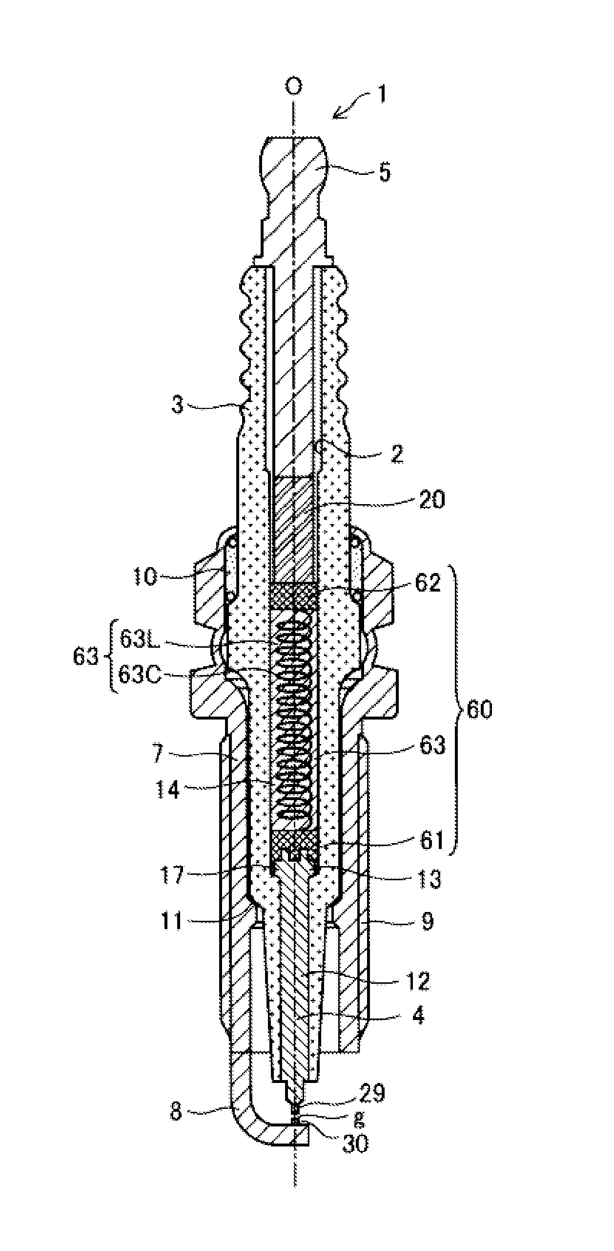
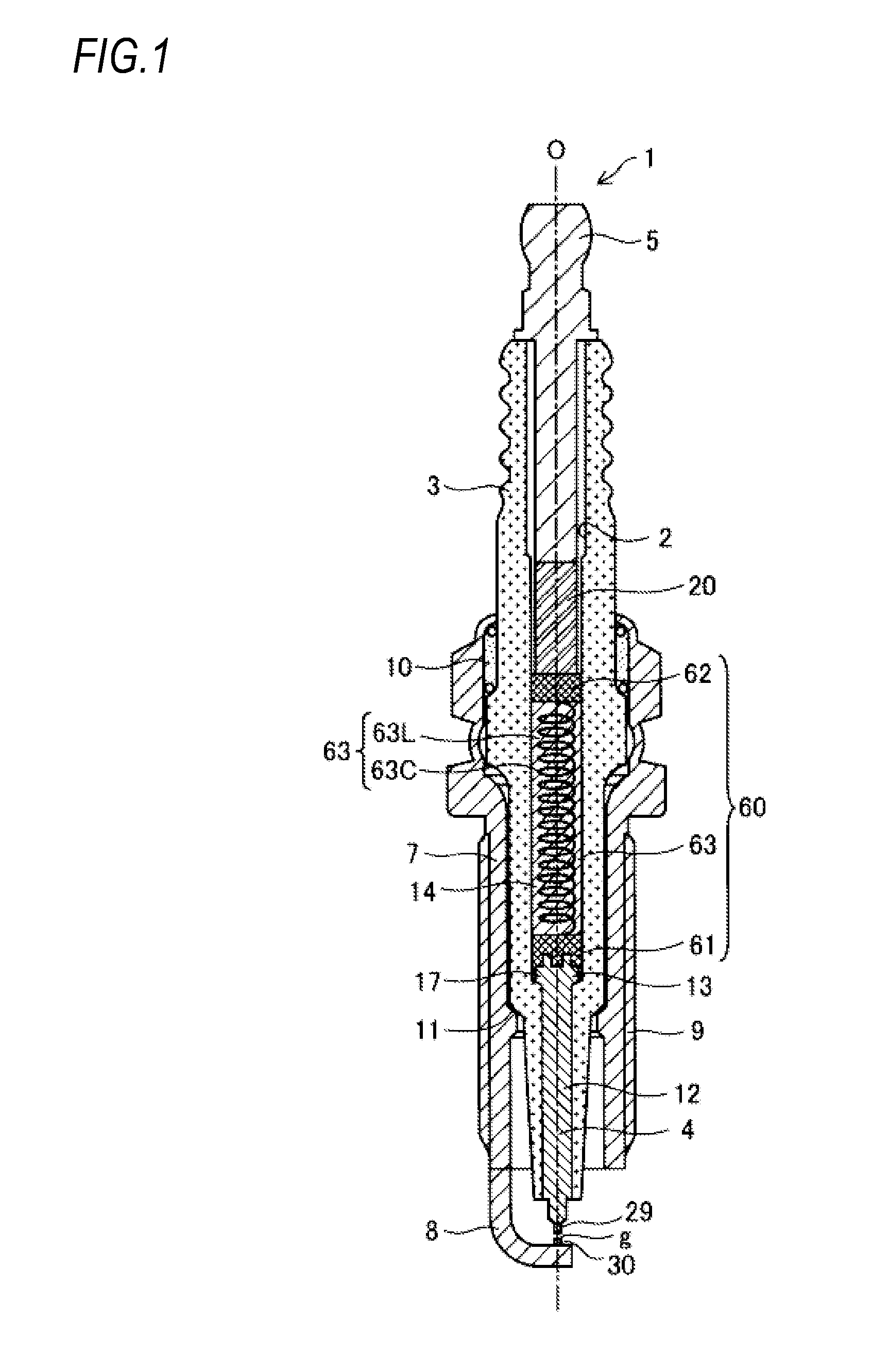
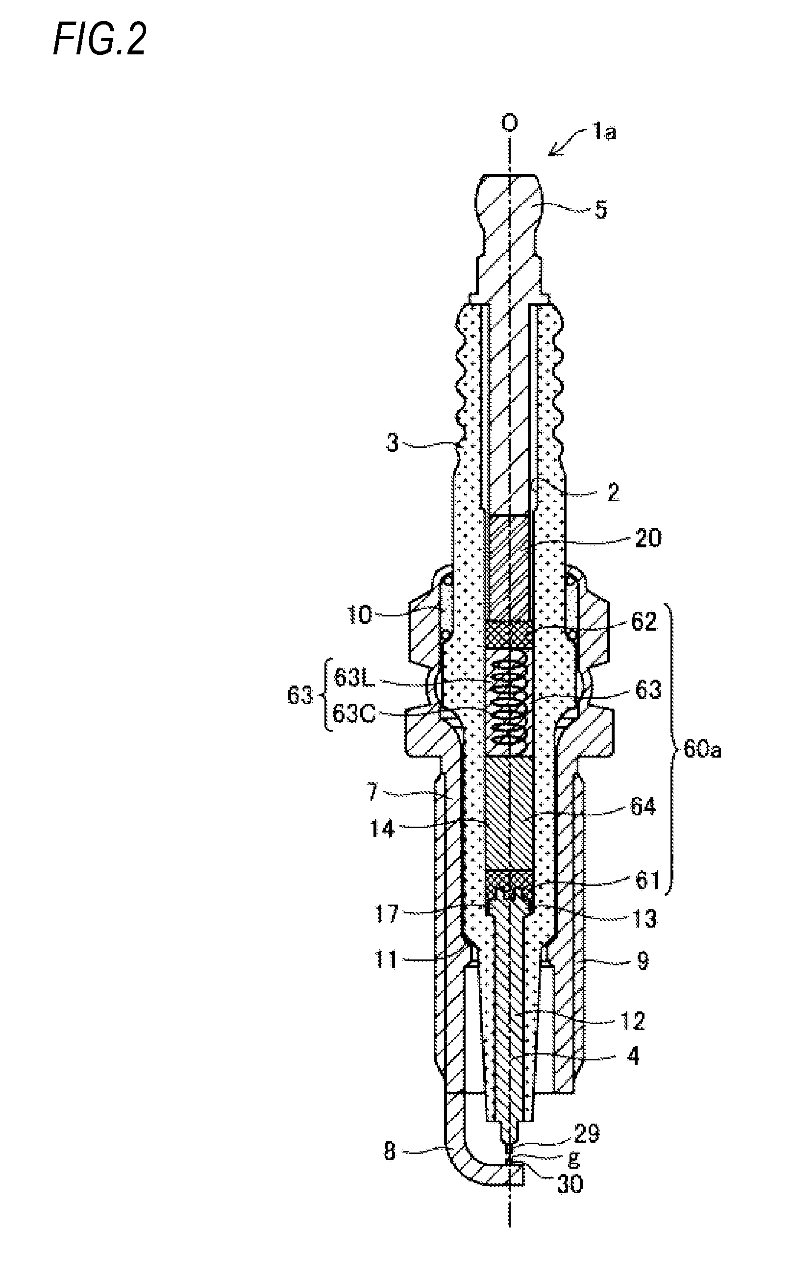
The patent text describes a metal wire structure that reduces noise and has a longer-lasting effect compared to other alternatives. The spiral structure of the wire helps to reduce noise and can be easily fixed in place, reducing the risk of wire disconnection. The wire diameter should be at least 0.1 mm to effectively reduce noise. If the wire is too thin, it may not provide enough noise reduction. An outer diameter of at least 1.0 mm is needed for sufficient noise reduction, and a pitch of at least 0.3 mm is required to achieve a desired capacity. A height of at least 8 mm is also necessary for effective noise reduction. Overall, this metal wire structure provides better noise reduction and a more durable solution for reducing noise in electronic devices.

Problems solved by technology

If a wire diameter of the metal wire is 0.1 mm or greater, it is possible to make occurrence of wire disconnection difficult.
Thus, the noise reduction effect as the inductance component may be insufficient.

Method used


Image

  • Spark plug
  • Spark plug
  • Spark plug

Examples


examples

[0046]FIGS. 5A and 5B are diagrams illustrating configurations of the conductor 63 and various test results regarding samples S01 to S28 of the spark plugs as the example of the invention, and samples S31 to S40 of spark plugs as a comparative example. Left side columns of the diagrams illustrate the dimensions and the materials of the spiral structure metal wire 63L used in each sample, the materials of the ceramics phase 63C, alkali metal contents if the ceramics phase 63C contains the alkali-containing phase, and presence or absence of Si, B, and P.

[0047]For the dimensions of the spiral structure metal wire 63L, an outer diameter of the entire spiral structure, the spiral pitch, the wire diameter and the height of the spiral structure were respectively set. For the material of the metal wire, elemental metal such as Mo, W, Ti, Al, Zn, Ag, Fe, Ni, Cr, Sn, and Cu and an alloys such as the Permalloy (Fe—Ni alloy), Sendust (Fe—Si—Al alloy), Inconel (Ni—Cr—Fe alloy), SUS316, and SUS40...

modified embodiment 1

[0059]In the embodiments described above, the entire spiral structure metal wire 63L has the spiral structure. However, the spiral structure metal wire 63L may have a part in which the spiral structure does not exist (for example, a linear rod-shaped portion). That is, the spiral structure metal wire 63L may have the spiral structure portion in at least a portion thereof. However, if the entire spiral structure metal wire 63L has the spiral structure, it is preferable in that the noise reduction effect is increased to the maximum.

modified embodiment 2

[0060]With respect to the spark plug, the invention can be applied to a spark plug having various configurations other than that illustrated in FIGS. 1 and 2.

[0061]The invention provides illustrative, non-limiting aspects as follows:

[0062](1) According to an aspect of the invention, there is provided a spark plug including: an insulator having an axial hole extending in an axial direction; a center electrode held at one end side of the axial hole; a terminal electrode held at the other end side of the axial hole; an electrical connection portion electrically connecting the center electrode and the terminal electrode inside the axial hole; and a metal shell accommodating the insulator, wherein the electrical connection portion includes a conductor including a ceramic phase and a metal wire having a spiral structure portion, wherein the metal wire has a wire diameter of 0.1 mm or greater and 0.5 mm or smaller, and wherein the spiral structure portion of the metal wire is configured su...


PUM


Abstract

A spark plug including an insulator having an axial hole, a center electrode held at one end side and a terminal electrode held at the other end side of the axial hole, an electrical connection portion electrically connecting the center electrode and the terminal electrode inside the axial hole, wherein the electrical connection portion includes a conductor including a ceramic phase and a metal wire having a spiral structure portion, wherein the metal wire has a wire diameter of 0.1 mm or greater and 0.5 mm or smaller, and wherein the spiral structure portion of the metal wire is configured such that an outer diameter thereof is 1.0 mm or greater and 3 mm or smaller, a pitch thereof is 0.3 mm or greater and 1 mm or smaller, and a height thereof is 8 mm or greater and 30 mm or smaller.

Description

RELATED APPLICATION[0001]This application claims priority from Japanese Patent Application No. 2014-110755 filed on May 29, 2014, the entire contents of which are incorporated herein by reference.FIELD OF THE INVENTION[0002]The present invention relates to a spark plug.BACKGROUND OF THE INVENTION[0003]In general, a spark plug for use in an internal combustion engine includes a tubular metal shell, a tubular insulator that is disposed in an inner hole of the metal shell, a center electrode that is disposed in an axial hole of the insulator at a tip end side, a terminal electrode that is disposed in the axial hole at the other end side, and a ground electrode of which one end is connected to a tip end of the metal shell and the other end faces the center electrode and forms a spark discharge gap. Furthermore, a spark plug is also known in which a resistor is provided between a center electrode and a terminal electrode inside an axial hole for the purpose of preventing radio wave noise...

Claims


Application Information

Patent Timeline
Patent Type & Authority Applications(United States)
IPC IPC(8): H01T13/04
CPCH01T13/04H01T13/41
Inventor TAKAOKA, KATSUYAKUROSAWA, KAZUHIROTANAKA, KUNIHARUYOSHIDA, HARUKIKURONO, HIROKAZUHONDA, TOSHITAKA
Owner NGK SPARK PLUG CO LTD
Learn More