Current-voltage conversion amplifier circuit including multiplier and multi input amplifier

a current-voltage conversion and amplifier circuit technology, applied in the field of amplifier circuits, can solve the problems of increasing circuit area, high power consumption, and requiring a resistance of hundreds of ohms, and achieve the effect of reducing power consumption and circuit area

Inactive Publication Date: 2015-12-03
ELECTRONICS & TELECOMM RES INST
View PDF1 Cites 4 Cited by
  • Summary
  • Abstract
  • Description
  • Claims
  • Application Information

AI Technical Summary

Benefits of technology

[0006]The present invention provides a current-voltage conver...

Problems solved by technology

However, the transimpedance amplifier requires a resistance of hundreds of ohms to process a small current signal.
Therefore, when the trans...

Method used


Image

  • Current-voltage conversion amplifier circuit including multiplier and multi input amplifier
  • Current-voltage conversion amplifier circuit including multiplier and multi input amplifier
  • Current-voltage conversion amplifier circuit including multiplier and multi input amplifier

Examples


Embodiment Construction

[0032]Various modifications are possible in various embodiments of the present invention and specific embodiments are illustrated in drawings and related detailed descriptions are listed. Accordingly, the present invention is not intended to limit specific embodiments and is understood that it should include all modifications, equivalents, and substitutes within the scope and technical range of the present invention.

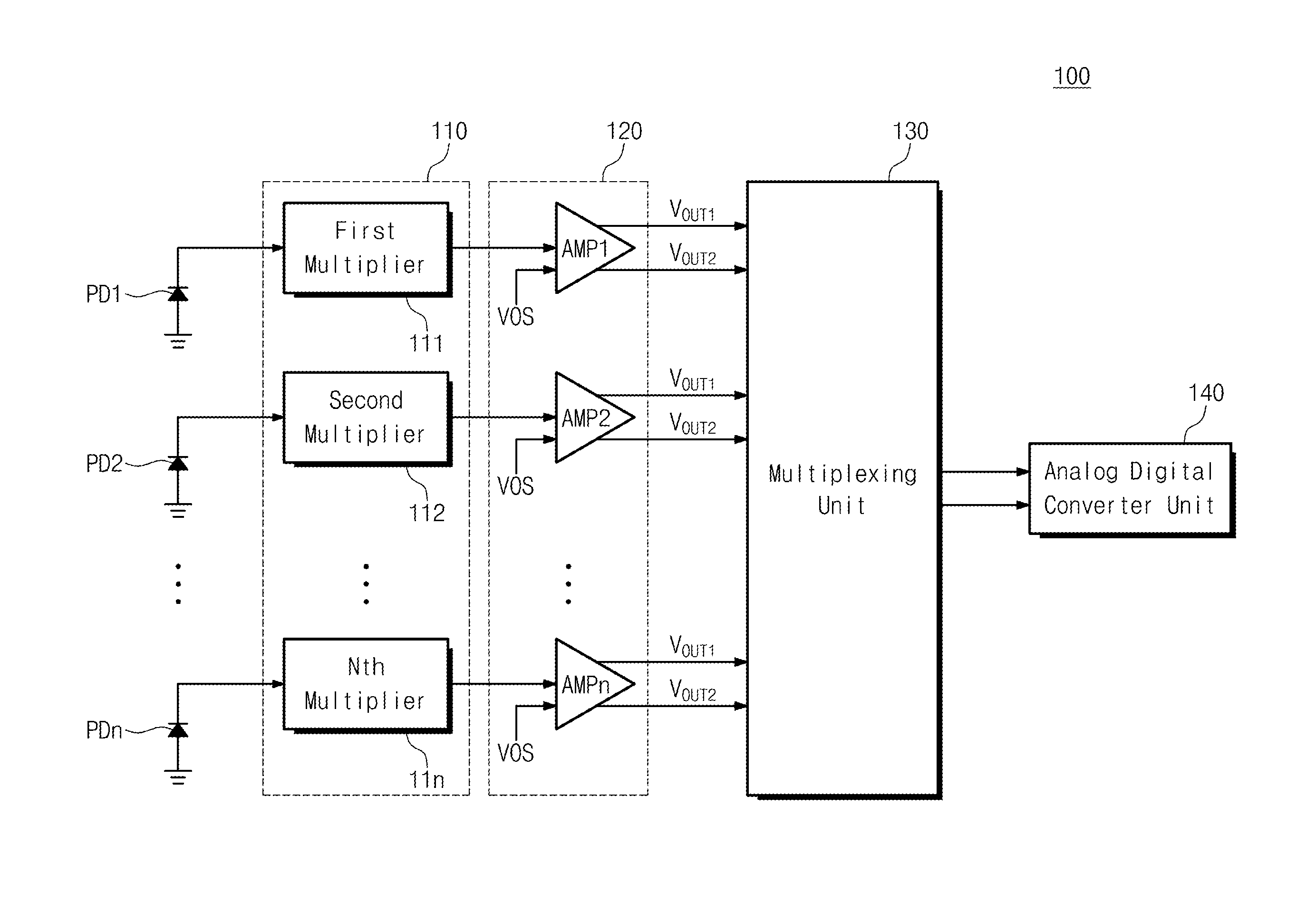
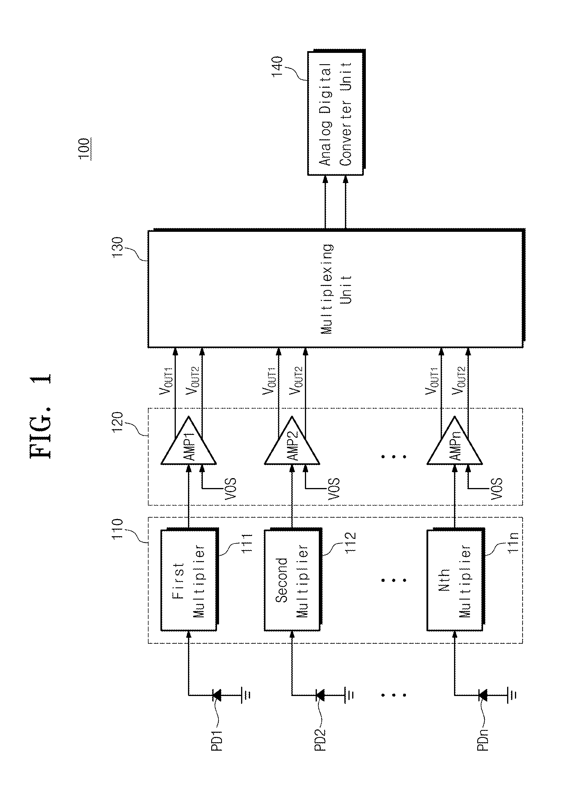
[0033]FIG. 1 is a block diagram illustrating a current-voltage conversion amplifier circuit according to an embodiment of the present invention. Referring to FIG. 1, a current-voltage conversion amplifier circuit 100 includes first to nth light receiving devices PD1 to PDn, a multiplier unit 110, a multi input amplifier unit 120, a multiplexing unit 130, and an analog digital converter (ADC) unit 140.

[0034]The first to nth light receiving devices PD1 to PDn, as a device converting optical signal into current signal, may include photodiodes and photo transistors. As light...


PUM


Abstract

Provided is a current-voltage conversion amplifier circuit including: a plurality of light receiving devices generating a current signal proportional to an amount of light by receiving the light; multipliers amplifying the current signal, converting the amplified current signal into a first voltage signal, outputting the amplified current signal, or outputting the converted first voltage signal; multi input amplifiers outputting first and second output voltage pairs through a process for receiving output values of multipliers and an offset voltage and amplifying the received output values and offset voltage; a multiplexing unit selecting and outputting one first and second output voltage pair among the first and second output voltage pairs outputted from multi input amplifiers; and a signal conversion unit converting a difference value between first and second output voltages outputted from the multiplexing unit and outputting the converted digital signal.

Description

CROSS-REFERENCE TO RELATED APPLICATIONS[0001]This U.S. non-provisional patent application claims priority under 35 U.S.C. §119 of Korean Patent Application No. 10-2014-0066879, filed on Jun. 2, 2014, the entire contents of which are hereby incorporated by reference.BACKGROUND OF THE INVENTION[0002]The present invention disclosed herein relates to an amplifier circuit, and more particularly, to a current-voltage conversion amplifier circuit.[0003]An amplifier circuit means an electronic circuit amplifying the voltage, current, and power of an input signal to generate an output signal. The amplifier circuit includes a voltage amplifier circuit, a current amplifier circuit, a power amplifier circuit, and a current-voltage amplifier circuit converting current signal into voltage signal and amplifying it.[0004]A high-impedance preamplifier and a transimpedance amplifier are mainly used as the current-voltage conversion amplifier circuit. The high-impedance preamplifier improves the recep...

Claims


Application Information

Patent Timeline
IPC IPC(8): H03F3/08H03F3/72H03G3/00H03F3/45
CPCH03F3/082H03F3/45179H03F3/72H03F2203/45088H03F2200/231H03F2203/7215H03G3/008H03F3/087H03F3/45475H03F2203/45514H03F2203/45551H03F2203/45614H03M1/121
Inventor JEON, YOUNG-DEUKSUK, JUNG HEELYUH, CHUN-GIKIM, YI-GYEONGIM, JONG PILCHO, MIN-HYUNG
Owner ELECTRONICS & TELECOMM RES INST
Why Eureka
Try Eureka