Metal-based mounting board and method of manufacturing metal-based mounting board
Inactive Publication Date: 2015-12-03
SUMITOMO BAKELITE CO LTD
View PDF2 Cites 3 Cited by
Summary
Abstract
Description
Claims
Application Information
AI Technical Summary
This helps you quickly interpret patents by identifying the three key elements:
Problems solved by technology
Method used
Benefits of technology
Benefits of technology
The present invention provides a way to make a metal-based mounting board that is highly reliable. Additionally, the invention provides a method for effectively manufacturing this reliable mounting board.
Problems solved by technology
Since such devices include electronic components each having a large amount of heat generation, they are required to exhibit high heatradiation.
However, there is a problem in that since such devices have large heat fluctuation, it is impossible to make connection reliability of the electronic component to the circuit board sufficiently high.
Method used
Image
Click on the blue label to locate the original text in one second.
Reading with bidirectional positioning of images and text.
Examples
first embodiment
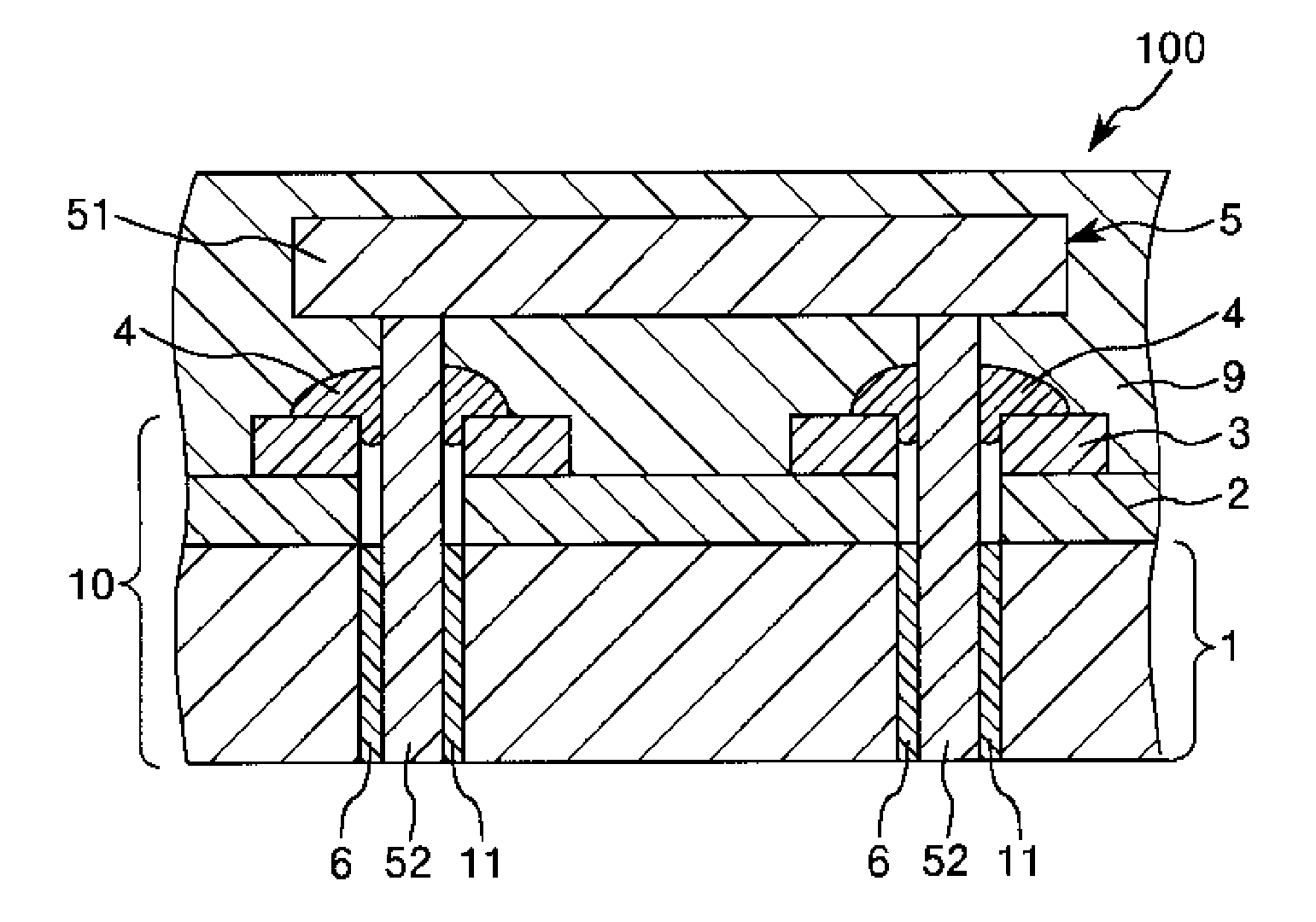
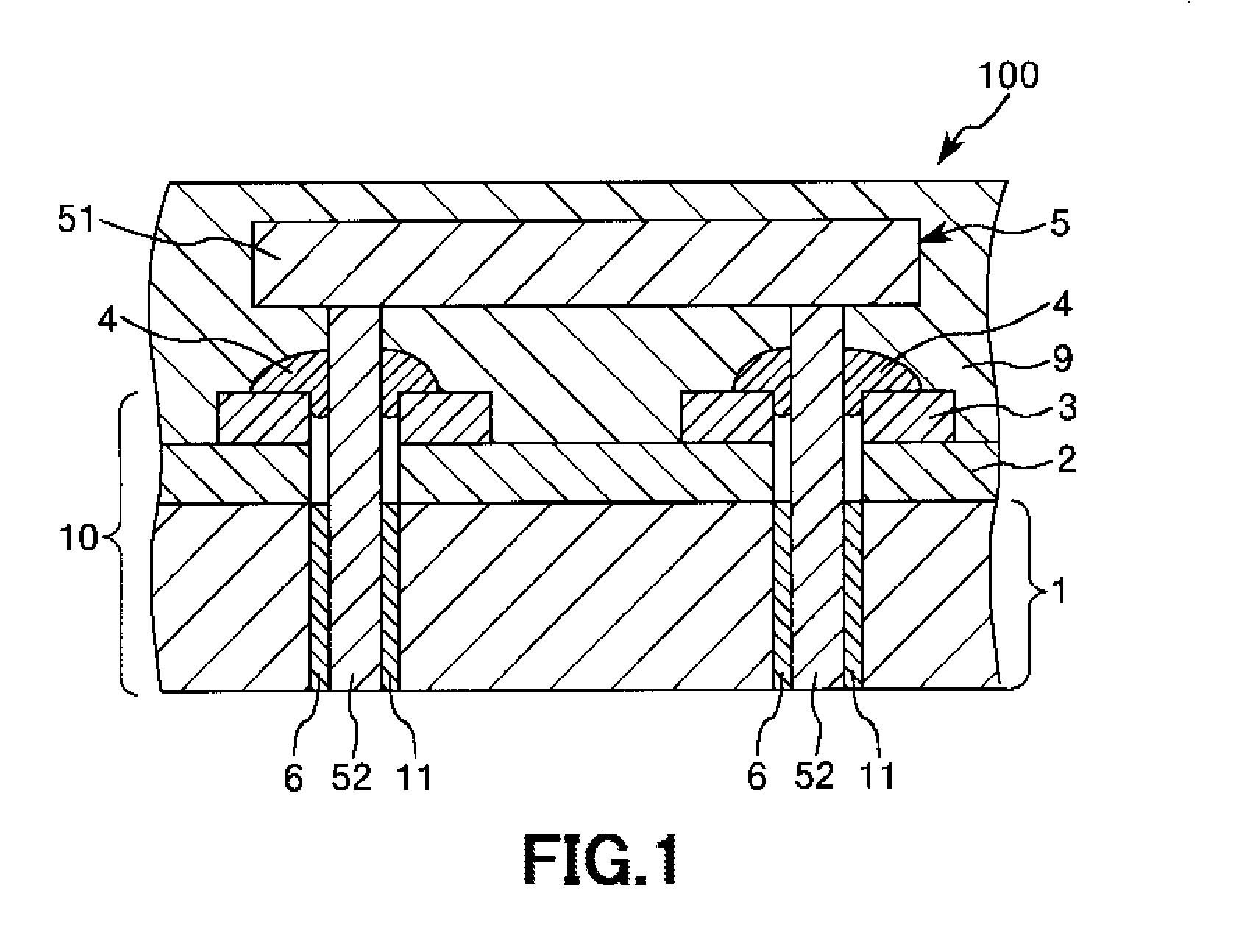
[0039]FIG. 1 is a vertical cross-sectional view schematically showing a first embodiment of the metal-based mounting board according to the present invention.
[0040]In this regard, in the following description, the upper side in FIG. 1 is referred to as the “upper”, the lower side therein is referred to as the “lower”, the right side therein is referred to as the “right”, and the left side therein is referred to as the “left”. Further, the drawings referred in this specification exaggeratingly show a part of components, and do not correctly reflect an actual size ratio and the like thereof.
[0041]A metal-based mounting board (an electronic device) 100 includes a metal-based circuit board 10, and an electronic component 5 provided on the metal-based circuit board 10.
[0042]The metal-based circuit board 10 includes a metal substrate 1, an insulating film 2 provided on the metal substrate 1, and a metal film 3 provided on the insulating film 2.
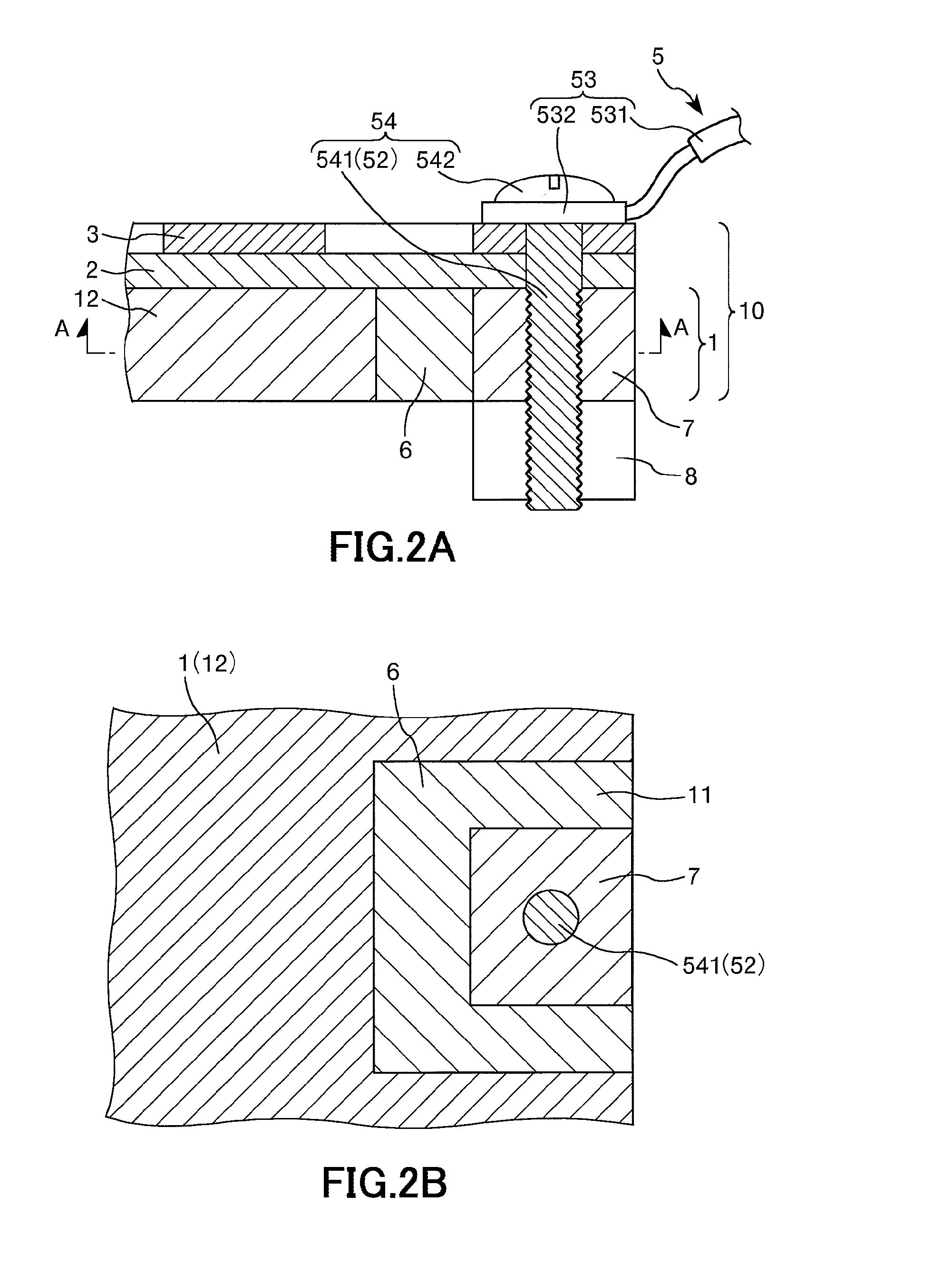
[0105]Next, a second embodiment of the metal-based mounting board according to the present invention will be described.
[0106]FIG. 2A is a vertical cross-sectional view schematically showing the second embodiment of the metal-based mounting board according to the present invention, FIG. 2B is a horizontal cross-sectional view schematically showing the second embodiment of the metal-based mounting board according to the present invention (a sectional view taken along line A-A of FIG. 1). Hereinafter, the second embodiment will be described with emphasis placed on points differing from the first embodiment. No description will be made on the same points.
[0107]As shown in FIG. 2B, in the metal-based mounting board 100 according to this embodiment, the through-hole 11 opens at an edge portion of the metal substrate 1. In this way, a whole circumference of the through-hole 11 need not be defined by the real portion 12.
[0108]Further, in this embodiment, a metal piece 7 is provided inside t...
PUM
Abstract
A metal-based mounting board according to the present invention includes: a metal-based circuit board including a metal substrate through which a through-hole is provided along a thickness direction thereof, an insulating film provided on the metal substrate and a metal film provided on the insulating film, wherein the through-hole opens on a surface of the metal film on the opposite side of the metal substrate via the insulating film and the metal film; an electronic component connected to the metal film, the electronic component including an electronic component main body and a conductive leg portion electrically connected to the electronic component main body and inserted into the through-hole; and an insulating portion provided at least between the leg portion locating inside the through-hole and the metal substrate, and having a function of preventing them from making contact with each other.
Description
CROSS-REFERENCE TO RELATED APPLICATION[0001]This application is based on and claims a priority from a Japanese Patent Application No. 2014-115046 filed on Jun. 3, 2014, which is hereby expressly incorporated by reference herein in its entirety.BACKGROUND OF THE INVENTION[0002]1. Field of the Invention[0003]The present invention relates to a metal-based mounting board and a method of manufacturing a metal-based mounting board.[0004]2. Description of the Related Art[0005]Conventionally, inverter devices or power semiconductor devices each of which is formed by mounting semiconductor elements such as an insulated gate bipolar transistor (IGBT) and a diode, and electronic components such as a resistance and a condenser on a circuit board are known.[0006]Since such devices include electronic components each having a large amount of heat generation, they are required to exhibit high heatradiation. In order to secure such high heatradiation, devices each having a structure in which a met...
Claims
Application Information
Patent Timeline
Application Date:The date an application was filed.
Publication Date:The date a patent or application was officially published.
First Publication Date:The earliest publication date of a patent with the same application number.
Issue Date:Publication date of the patent grant document.
PCT Entry Date:The Entry date of PCT National Phase.
Estimated Expiry Date:The statutory expiry date of a patent right according to the Patent Law, and it is the longest term of protection that the patent right can achieve without the termination of the patent right due to other reasons(Term extension factor has been taken into account ).
Invalid Date:Actual expiry date is based on effective date or publication date of legal transaction data of invalid patent.

