Overmolded tubing assembly and adapter for a positive displacement pump

a positive displacement, tubing technology, applied in the direction of positive displacement liquid engines, liquid fuel engines, soldering apparatuses, etc., can solve the problems of high system pressure and chemical flow rate, peristaltic hose pumps are considerably more expensive to operate (often three times more), and assemblies are susceptible to metal corrosion. corrosion, increase the effect of tube life and increased drive efficiency

Active Publication Date: 2015-12-10
BLUE WHITE INDS
View PDF3 Cites 4 Cited by
  • Summary
  • Abstract
  • Description
  • Claims
  • Application Information

AI Technical Summary

Benefits of technology

[0008]The present inventions relate to pumps and tubing assemblies that are configured to pump fluids at high pressures and high flow rates. More particularly, the tubing assemblies can comprise multiple small diameter tubes that replace the traditional single large diameter hose in peristaltic pumps. In particular, embodiments disclosed herein can enable pumping against high pressures while providing a high flow rate, increased tube life, increased drive efficiency, lower replacement cost, lower energy consumption, cooler operating temperatures, and reduced operating and maintenance costs. Additionally, the tubing assemblies can comprise an interchangeable adapter system that may require less inventory cost and take up less inventory space. In some embodiments, the adapter system may include a plurality of pump tubing grippers or locks, a plurality of adapter / external system interfaces, and a plurality of end fittings. These pieces may be used interchangeably to fit a variety of tubing profiles, including single or dual tube or multiple lumen tubing, and customer requirements. All of these advantages are achieved while implementing designs that contrast with the traditional industry standard and knowledge. Similar tubing and adapter designs are disclosed in U.S. patent application Ser. No. 14 / 195,678, entitled “HIGH PRESSURE, HIGH FLOW RATE TUBING ASSEMBLY AND ADAPTER FOR A POSITIVE DISPLACEMENT PUMP,” filed on Mar. 3, 2014, which is hereby incorporated by reference in its entirety.

Problems solved by technology

These assemblies are susceptible to metal corrosion due to the leakage of fumes into the pump head housing.
However, system pressures and chemical flow rates often exceed the capabilities of existing peristaltic “tube” pumps.
Peristaltic hose pumps are considerably more expensive to operate (often three times more) because they use large, high-torque, high-horsepower AC drives.
Although peristaltic pumps have gained widespread popularity, the effectiveness of current peristaltic pumps is severely limited by the design of the tube or hose.
However, using a large diameter tube or hose at high pressure also requires a larger wall thickness in order to withstand the high pressure and avoid “ballooning.” Tubing in a peristaltic pump tends to expand or balloon at the outlet side where system pressure is exerted, and the effects of the ballooning and relaxing of the tubing can build up over time.
These challenges only increase as the required operating pressure is increased.
For example, as noted above, having a large wall thickness to achieve high pressures can cause additional load to the pump drive.
Tube diameter expansion (ballooning) can occur on pressure side of pump, which can require additional pump drive load to overcome tube diameter expansion (ballooning) and may result in early tube rupture.
In pumps having a glycerin-filled pump head (which is used to reduce friction and heat), tube rupture can cause glycerin to enter the fluid path and contaminate the system.

Method used


Image

  • Overmolded tubing assembly and adapter for a positive displacement pump
  • Overmolded tubing assembly and adapter for a positive displacement pump
  • Overmolded tubing assembly and adapter for a positive displacement pump

Examples


Embodiment Construction

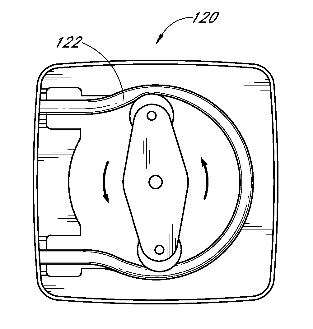
[0056]While the present description sets forth specific details of various embodiments, it will be appreciated that the description is illustrative only and should not be construed in any way as limiting. Furthermore, various applications of such embodiments and modifications thereto, which may occur to those who are skilled in the art, are also encompassed by the general concepts described herein. In the description that follows, a peristaltic pump tubing assembly may include a tube or lumen. The terms “tube” and “lumen” are not synonymous. However, in the following description, the term “tube” is used generally to refer to peristaltic pump tubing which may also include one or more lumens.

[0057]As noted above, embodiments of the present inventions can overcome several prior art deficiencies and provide advantageous results. Some embodiments provide for a peristaltic pump that can operate at high pressures while maintaining a high flow rate. Some embodiments therefore allow the peri...


PUM

PropertyMeasurementUnit
diameteraaaaaaaaaa
flow rateaaaaaaaaaa
flow rateaaaaaaaaaa

Abstract

A tubing assembly is provided that can comprise a plurality of tubes or lumens that can be disposed within a head of a peristaltic pump. The tubing assembly can provide a flow rate or volume capacity that is generally equal to or greater than that achieved with a comparable prior art tube while operating at higher pressures than that possible using the prior art tube. Further, in accordance with some embodiments, the tubing assembly can achieve a longer working life than a comparable prior art tube, and the load on the pump motor can be reduced such that the pump life is increased and/or a larger pump motor is not required to achieve such advantageous results.

Description

INCORPORATION BY REFERENCE TO ANY PRIORITY APPLICATIONS[0001]Any and all applications for which a foreign or domestic priority claim is identified in the Application Data Sheet as filed with the present application are hereby incorporated by reference under 37 CFR 1.57.[0002]This application claims the benefit of U.S. Provisional Patent Application No. 62 / 009,858, entitled “OVERMOLDED TUBING ASSEMBLY AND ADAPTER FOR A POSITIVE DISPLACEMENT PUMP,” filed on Jun. 9, 2014, which is hereby incorporated by reference in its entirety.FIELD OF THE INVENTION[0003]The present inventions relate to tubing assemblies, and more specifically to tubing assemblies for use with peristaltic pumps.DESCRIPTION OF THE RELATED ART[0004]A peristaltic roller pump typically has two or more rollers, but may have other configurations. The rollers are generally spaced circumferentially evenly apart and are mounted on a rotating carrier that moves the rollers in a circle. A length of flexible tubing may be placed...

Claims


Application Information

Patent Timeline
Patent Type & Authority Applications(United States)
IPC IPC(8): F04B45/08F04B53/16F04B43/08
CPCF04B45/08Y10T29/49238F04B53/16F04B43/082F04B43/1261F04B43/1284F04B43/1292A61M39/10B23K35/0261B23K35/22B23K35/3053B23K35/3086C22C38/26C22C38/28C22C38/32F04B43/0072F16L11/22F16L39/02
Inventor GLEDHILL, III, ROBERTNGUYEN, JOHNSMITH, STEVEN LEE
Owner BLUE WHITE INDS
Why Eureka
Try Eureka