
System and Method for Protecting Rotary Machines

Active Publication Date: 2015-12-10
GENERAL ELECTRIC CO
View PDF1 Cites 13 Cited by
  • Summary
  • Abstract
  • Description
  • Claims
  • Application Information

AI Technical Summary

Benefits of technology

The present patent is related to a system and method for protecting a rotary machine from damage caused by imbalance within its components. The system includes sensors that measure vibrations during operation and a processor that filters the measured vibrations to identify signals that exceed a threshold amplitude, indicating an imbalance. The system can then perform corrective actions to protect the rotary machine, such as shutting down or de-rating it. The technical effect of this patent is to provide a reliable system for identifying and addressing imbalance in rotary machines to prevent damage and ensure efficient operation.

Problems solved by technology

During installation and / or operation of a rotary machine, it is common for the machine to become imbalanced.
For example, during installation of a wind turbine, faulty blade-zero marking or high pitch offsets may result in excessive vibration in the generator frame.
In addition, manufacturing tolerances of the generator typically cause the generator to have a mass imbalance about its longitudinal axis, which causes vibrations within the wind turbine.
Rotary machines are designed to withstand a certain amount of vibrations; however, excessive vibrations can lead to the eventual wearing out, or even sudden failure, of machine parts.
Further, replacement of vibration-worn parts of the rotary machine can require the unit to be taken off-line, increasing both time and expenses associated with the rotary machine.
Such a control technology involves complex calculations and is sensitive to noise within the vibration signal that can lead to skewed results or incorrect detection of a particular frequency in the output signal.

Method used


Image

  • System and Method for Protecting Rotary Machines
  • System and Method for Protecting Rotary Machines
  • System and Method for Protecting Rotary Machines

Examples


Embodiment Construction

[0027]Reference now will be made in detail to embodiments of the invention, one or more examples of which are illustrated in the drawings. Each example is provided by way of explanation of the invention, not limitation of the invention. In fact, it will be apparent to those skilled in the art that various modifications and variations can be made in the present invention without departing from the scope or spirit of the invention. For instance, features illustrated or described as part of one embodiment can be used with another embodiment to yield a still further embodiment. Thus, it is intended that the present invention covers such modifications and variations as come within the scope of the appended claims and their equivalents.

[0028]Generally, the present disclosure is directed to a system and method for identifying an imbalance within a rotary machine in a high noise environment and protecting the rotary machine from damage caused by the imbalance. More specifically, in one embo...


PUM


Abstract

The present disclosure is directed to a system and method for protecting a rotary machine in a high noise environment. In one embodiment, the method includes a step of measuring a vibration signal during operation of the rotary machine. Another step includes modulating the vibration signal at a desired frequency to generate a modulated signal having a direct current (DC) value. The desired frequency varies as a function of an operational parameter of the rotary machine. The method also includes a step of filtering the modulated signal via one or more low-pass filters. Another step includes comparing an amplitude of the filtered signal to a threshold amplitude for one or more components of the rotary machine. The threshold amplitude is indicative of an imbalance within one or more components of the rotary machine. The rotary machine is then operated based on the comparison so as to protect the rotary machine from damage caused by the imbalance within the one or more components of the rotary machine.

Description

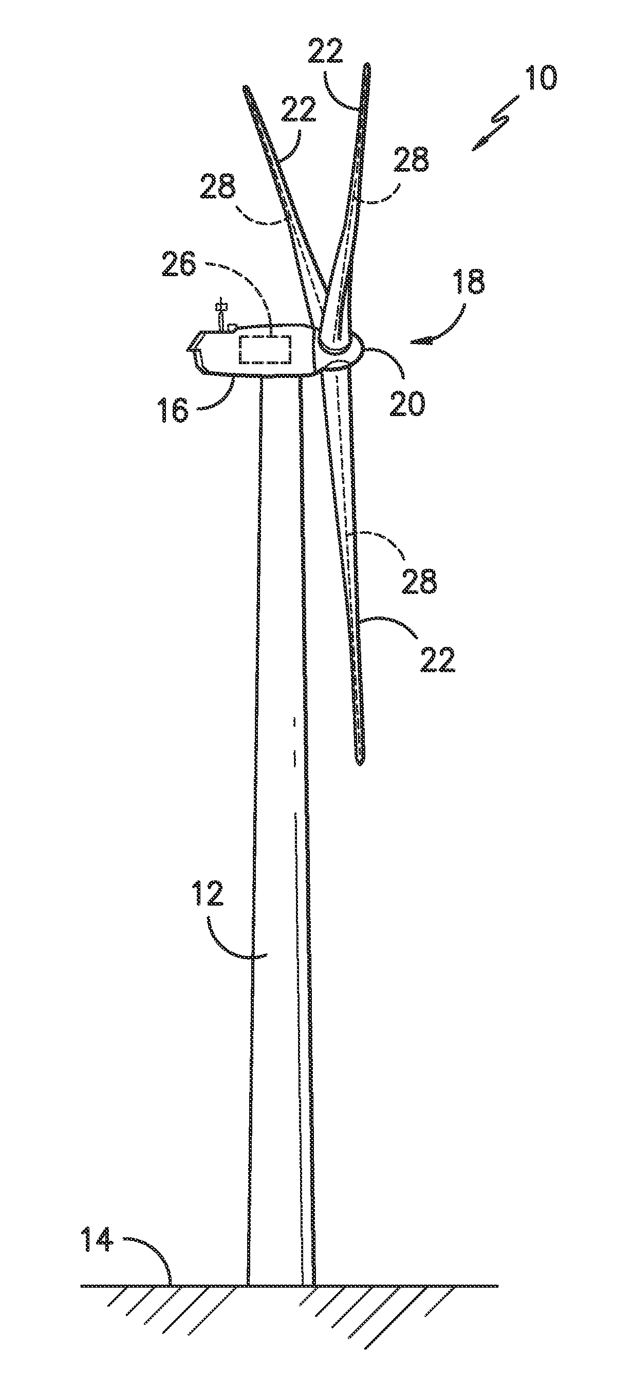
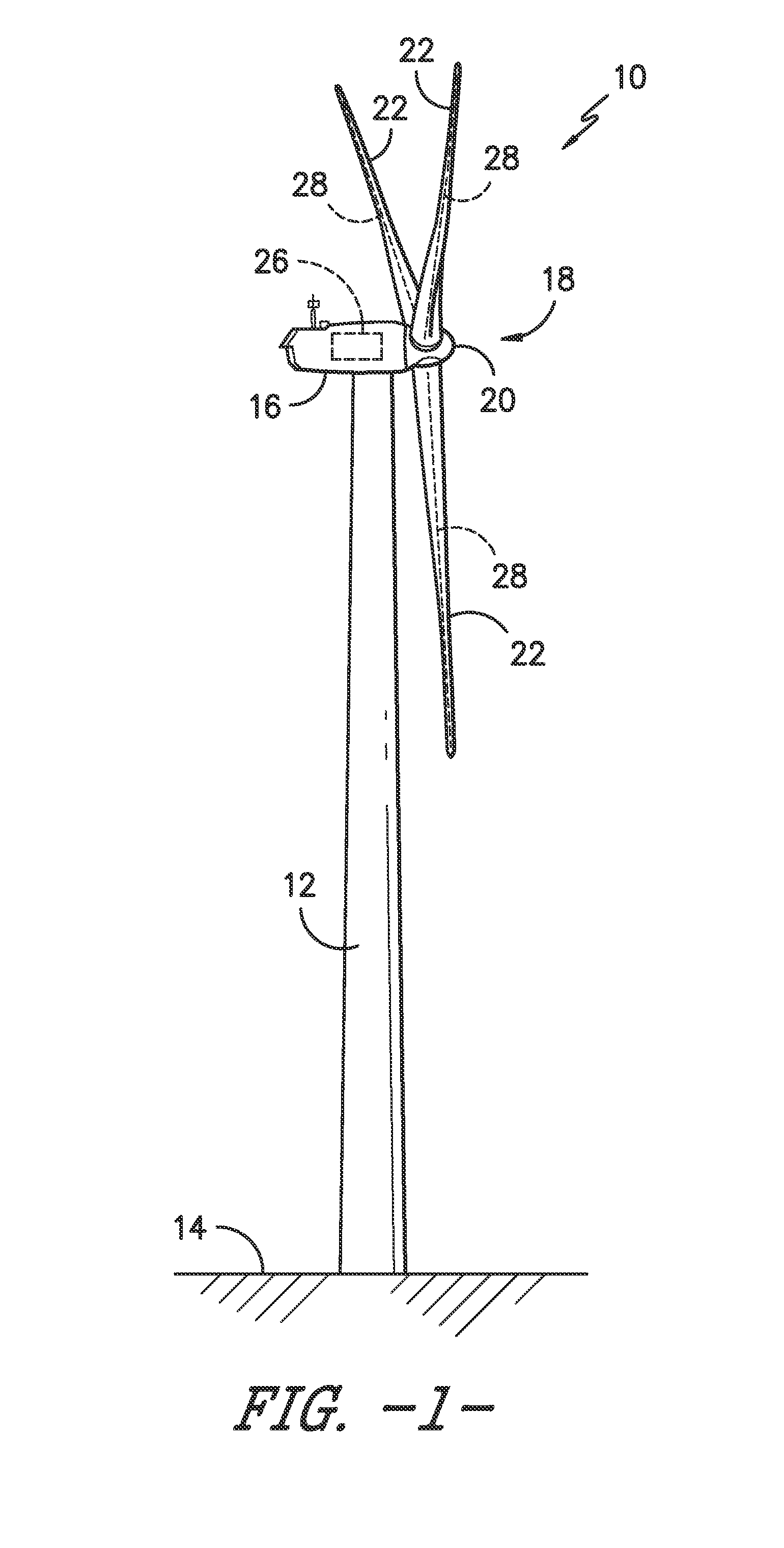
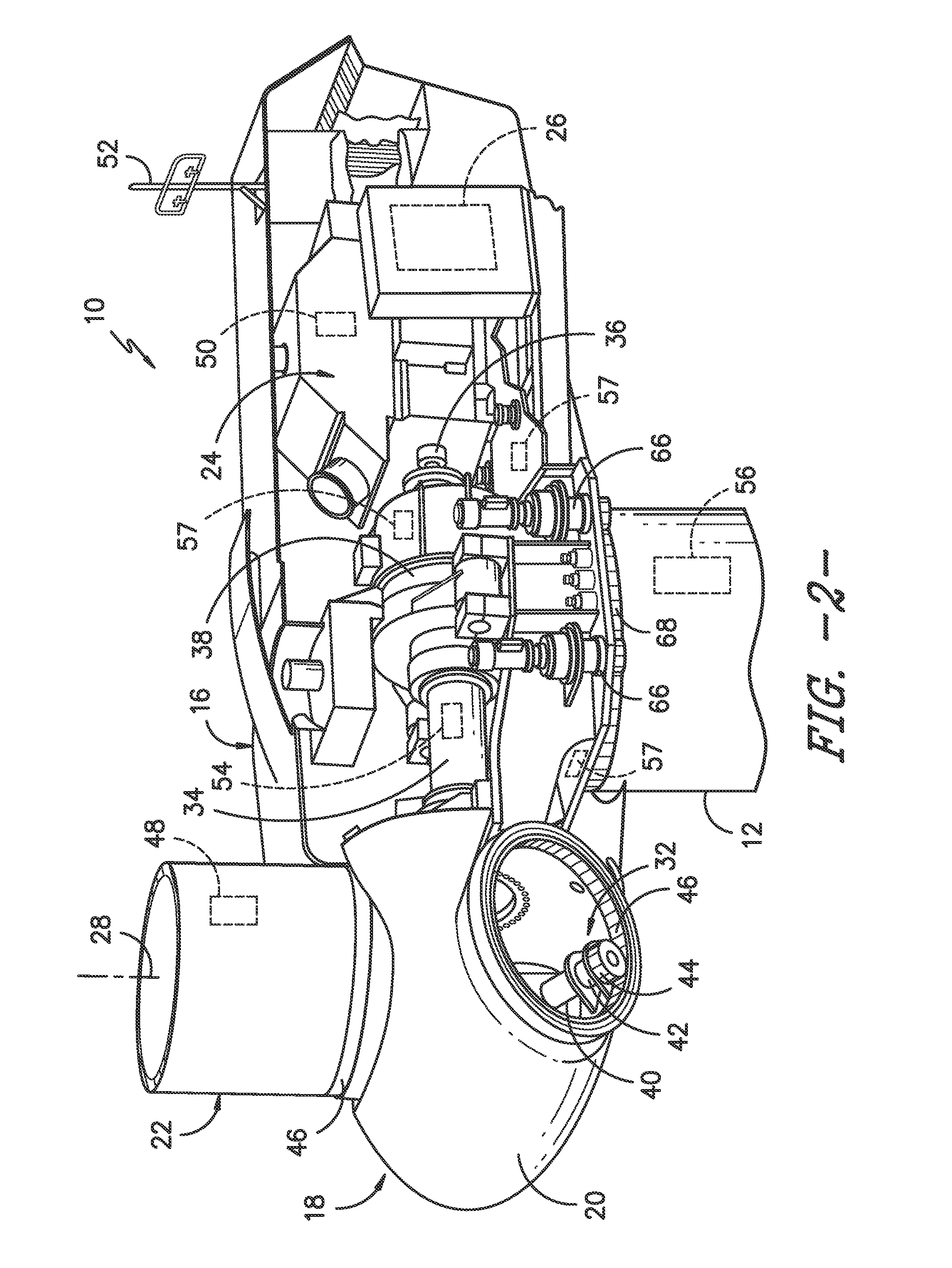
FIELD OF THE INVENTION[0001]The present invention relates generally to rotary machines, and more particularly to a system and method for protecting rotary machines using a simple, frequency discriminator.BACKGROUND OF THE INVENTION[0002]Rotary machines include, such as large turbine-generator units having gas, steam, or wind turbines which turn generators to produce electric power. Wind power is considered one of the cleanest, most environmentally friendly energy sources presently available, and wind turbines have gained increased attention in this regard. A modern wind turbine typically includes a tower, a generator, a gearbox, a nacelle, and a rotor. The rotor typically includes a rotatable hub having one or more rotor blades attached thereto. The rotor blades capture kinetic energy of wind using known airfoil principles. The rotor blades transmit the kinetic energy in the form of rotational energy so as to turn a shaft coupling the rotor blades to a gearbox, or if a gearbox is no...

Claims


Application Information

Patent Timeline
IPC IPC(8): G01M1/22
CPCG01M1/22F03D13/35G01H1/003Y02E10/72
Inventor CARDINAL, MARK EDWARDGANDHI, JIGNESH GOVINDLALDEWEY, ROBERT J.CLOSE, RYAN SPENCERDINJUS, THOMAS ERNSTMOVISCHOFF, BERNARDO ADRIANKORIM, DAVID CHARLES
Owner GENERAL ELECTRIC CO
Features
  • Generate Ideas
  • Intellectual Property
  • Life Sciences
  • Materials
  • Tech Scout
  • Unparalleled Data Quality
  • Higher Quality Content
  • 60% Fewer Hallucinations
Learn More