
Simultaneous mr imaging method and apparatus for simultaneous multi-nuclear mr imaging

a multi-nuclear and simultaneous imaging technology, applied in the direction of magnetic measurements, instruments, measurement devices, etc., can solve the problems of poor signal-to-noise ratio, patient position may have changed, serial mr imaging using different types of atoms is more time-consuming, etc., to achieve faster, less error-prone and convenient mr imaging

Inactive Publication Date: 2015-12-10
SIEMENS AG
View PDF5 Cites 4 Cited by
  • Summary
  • Abstract
  • Description
  • Claims
  • Application Information

AI Technical Summary

Benefits of technology

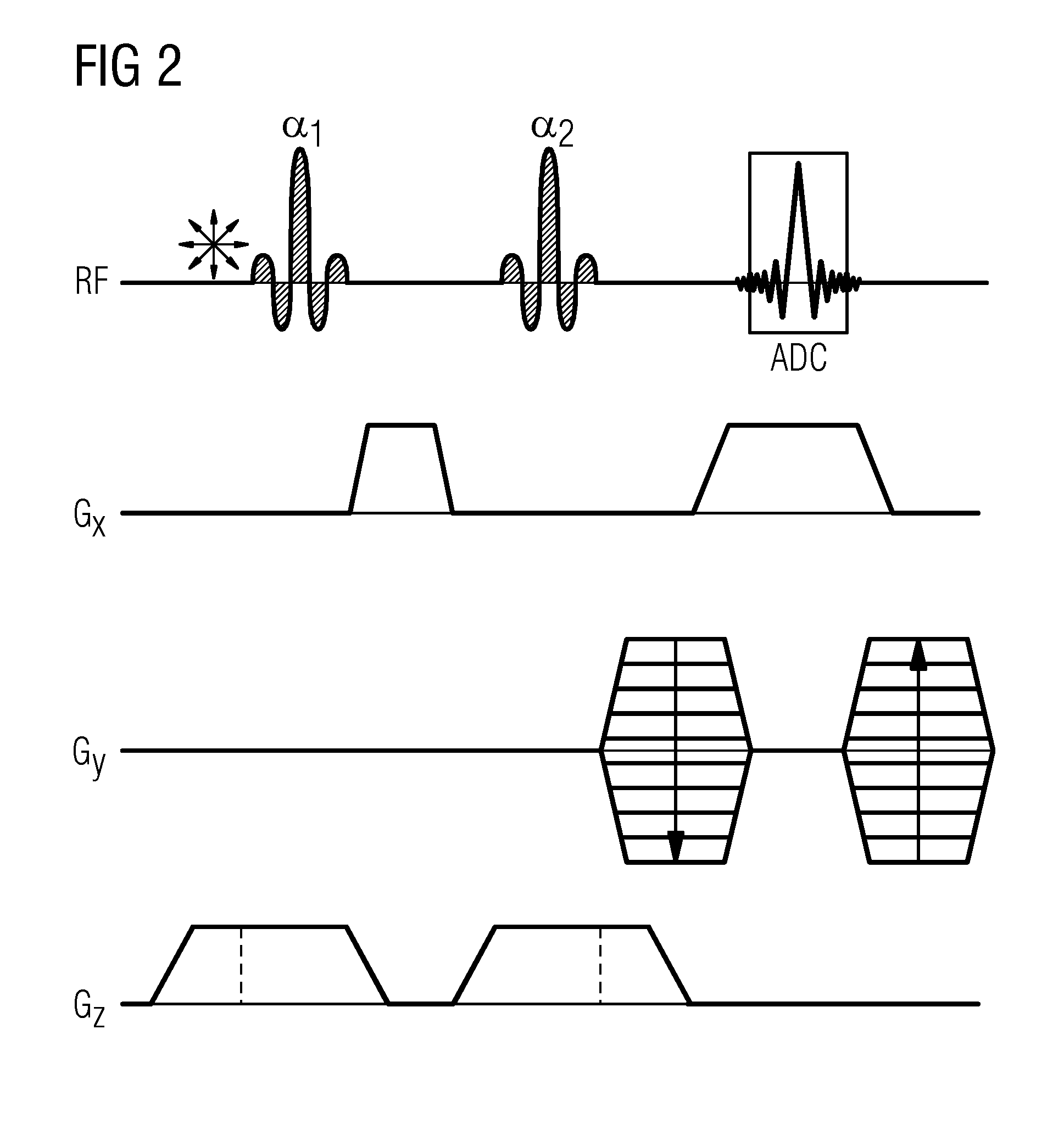
The invention allows for simultaneous excitation and reading of different types of atoms using MR imaging. A multi-resonant RF excitation pulse is transmitted with different sub-signals for different atom types, and a common gradient scheme is transmitted to facilitate unambiguous spatial assignment of received signals. The received echo signal is separated into individual signals with different frequencies, which can be easily filtered out. The image data is reconstructed from the raw data obtained from the separated individual signals. The invention is optimized for hydrogen atoms to produce a high-quality image with minimal interference effects.

Problems solved by technology

The challenges of Na23 MRT imaging result, one the one hand, from a poorer SNR (signal-to-noise ratio).
However, serial MR imaging using different types of atom is more time-consuming.
In addition, with serial scanning the problem arises that the patient's position may have changed between the scans.
Moreover, during serial acquisition, effects due to respiration, heartbeat and similar changes can have different effects on the consecutively acquired images because of the different acquisition times. This makes it more difficult to compare the serial scans performed using different types of atom.

Method used


Image

  • Simultaneous mr imaging method and apparatus for simultaneous multi-nuclear mr imaging
  • Simultaneous mr imaging method and apparatus for simultaneous multi-nuclear mr imaging
  • Simultaneous mr imaging method and apparatus for simultaneous multi-nuclear mr imaging

Examples


Embodiment Construction

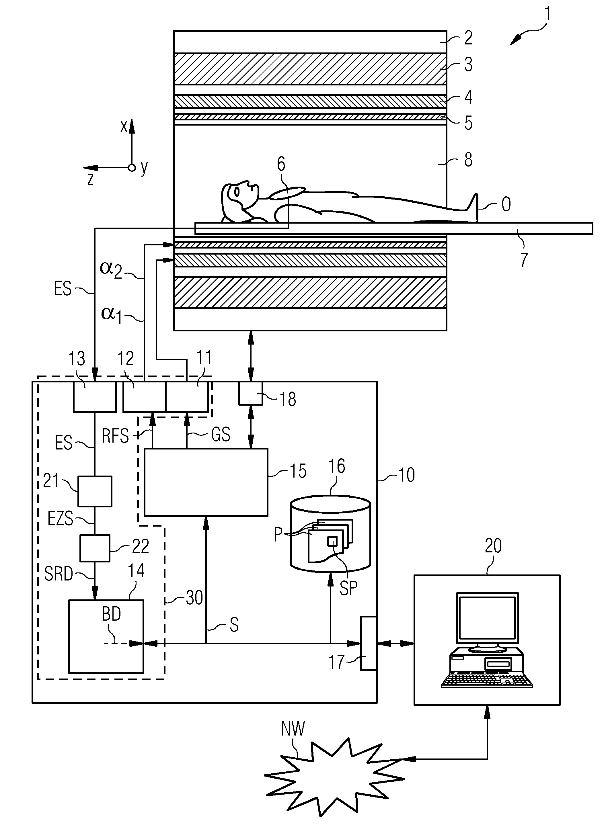
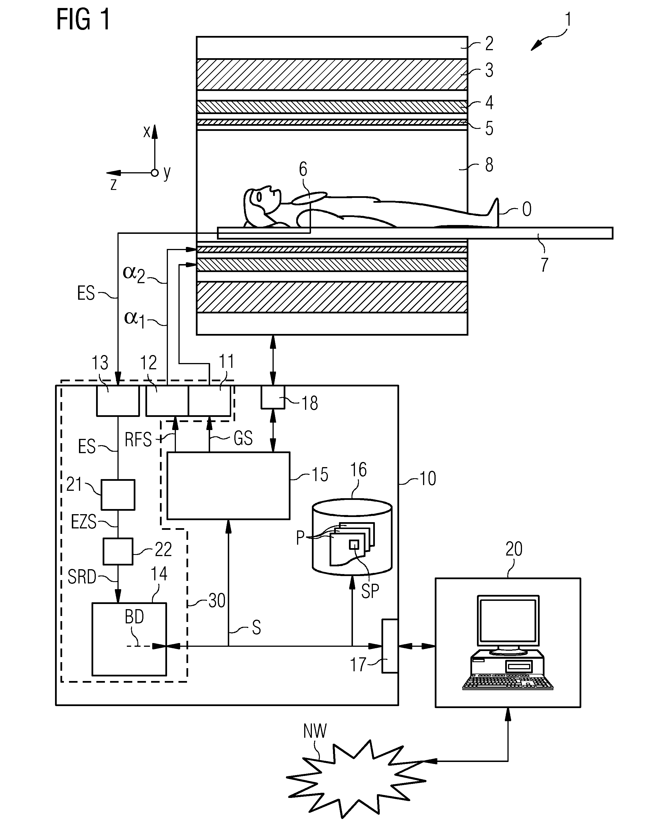
[0032]FIG. 1 shows an extremely schematic representation of a magnetic resonance system 1. It comprises on the one hand the actual magnetic resonance scanner 2 incorporating a scanning chamber 8 or patient tunnel 8. A couch 7 can be moved into said patient tunnel 8 so that during a scan a patient O or examinee lying thereon can be supported in a particular position inside the magnetic resonance scanner 2 relative to the magnet system and radiofrequency system disposed therein, or can also be moved between different positions during a scan.

[0033]The basic components of the magnetic resonance scanner 2 are a main field magnet 3, a gradient system 4 having magnetic field gradient coils for generating magnetic field gradients in the x-, y- and z-directions, and an RF body coil 5. The magnetic field gradient coils in the x-, y- and z-direction can be controlled independently of one another so that, by means of a predefined combination, gradients can be applied in any logical spatial dire...


PUM


Abstract

A simultaneous MR imaging method is described in which different types of atom are simultaneously excited and read out. First a multi-resonant RF excitation pulse is transmitted including a plurality of sub-signals assigned to different types of atom and having different frequency ranges. Simultaneously or in a synchronized manner, a gradient scheme common to the different types of atom is transmitted with which an unambiguous spatial assignment of received signals can be performed. In the subsequent readout process, an echo signal is received including different individual echoes of different types of atom. The received echo signal is separated into individual signals. Finally, image data is reconstructed from raw data obtained from the separated individual signals. Also described is an apparatus with which the above described method can be carried out.

Description

CROSS-REFERENCE TO RELATED APPLICATION[0001]This application claims priority to DE 102014210599.4 having a filing date of Jun. 4, 2014, the entire contents of which are hereby incorporated by reference.FIELD OF TECHNOLOGY[0002]The following relates to a simultaneous MR imaging method and to an apparatus for simultaneous imaging. The following also relates to a magnetic resonance system.BACKGROUND[0003]In a magnetic resonance system, also known as a magnetic resonance tomography system, the body being scanned is exposed to a relatively high main magnetic field of e.g. 1, 3, 5 or 7 teslas using a main field magnet system. In addition, a gradient system is used to apply a magnetic field gradient. Radiofrequency excitation signals (RF signals) are then emitted via a radiofrequency transmitting system using suitable antenna devices, which is designed to cause the nuclear spins of particular atoms resonantly excited by this radiofrequency field to be tilted by a defined flip angle relativ...

Claims


Application Information

Patent Timeline
IPC IPC(8): G01R33/561G01R33/385G01R33/30
CPCG01R33/5612G01R33/385G01R33/307G01R33/5615G01R33/4828G01R33/4833
Inventor FISCHER, HUBERTUSKRIEG, ROBERTRUFF, JAN
Owner SIEMENS AG
Learn More