
Vehicle audio system and noise removal method thereof

a technology of vehicle audio and noise removal, which is applied in the direction of noise generation, amplifiers with semiconductor devices/discharge tubes, instruments, etc., can solve the problems of large heat, large amount of heat, and inability to convert the form of an audio amplifier stage into digital form, etc., and achieve the effect of efficient removal of nois

Active Publication Date: 2015-12-10
HYUNDAI MOTOR CO LTD
View PDF2 Cites 0 Cited by
  • Summary
  • Abstract
  • Description
  • Claims
  • Application Information

AI Technical Summary

Benefits of technology

The present patent provides a vehicle audio system and a noise removal method that can efficiently remove noise generated when processing broadcast signals using a full digital amplifier. This method allows for optimal sampling frequency to be determined based on the detected frequency of a selected radio broadcast, resulting in improved reception performance and prevention of deterioration in performance without adding any additional physical / hardware components. This method may be readily implemented in an actual vehicle audio system without an increase in cost.

Problems solved by technology

Currently, the process of converting the form of an audio amplifier stage into digital form is unsatisfactory, and therefore, the conventional analog scheme is frequently used.
However, the conventional amplifier generates a large amount of heat in an amplifier circuit, and accordingly, the size of a heat sink is also relatively large.
As the size of the heat sink increases, the design of the vehicle becomes increasingly limited, and the fuel efficiency of the vehicle is also decreased.
In addition, a complicated circuit may be necessary to remove noise.
Third, noise is moved posterior to the audio frequency through the noise shaping technique.
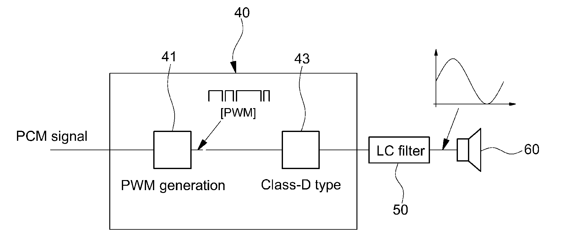
However, in the conventional audio amplifier to which the full digital amplifier is applied, there is a problem in that harmonic noise can be generated in the period of a sampling frequency when a digital signal is sampled at high frequency in signal processing.

Method used


Image

  • Vehicle audio system and noise removal method thereof
  • Vehicle audio system and noise removal method thereof
  • Vehicle audio system and noise removal method thereof

Examples


Embodiment Construction

[0032]Hereinafter, reference will be made in detail to embodiments of the present disclosure, examples of which are illustrated in the accompanying drawings and described below. While the disclosure will be described in conjunction with embodiments, it will be understood that present description is not intended to limit the disclosure to those embodiments. On the contrary, the disclosure is intended to cover not only the disclosed embodiments, but also various alternatives, modifications, equivalents and other embodiments, which may be included within the spirit and scope of the disclosure as defined by the appended claims.

[0033]The terminology used herein is for the purpose of describing particular embodiments only and is not intended to be limiting of the disclosure. As used herein, the singular forms “a”, “an” and “the” are intended to include the plural forms as well, unless the context clearly indicates otherwise. It will be further understood that the terms “comprises” and / or ...


PUM


Abstract

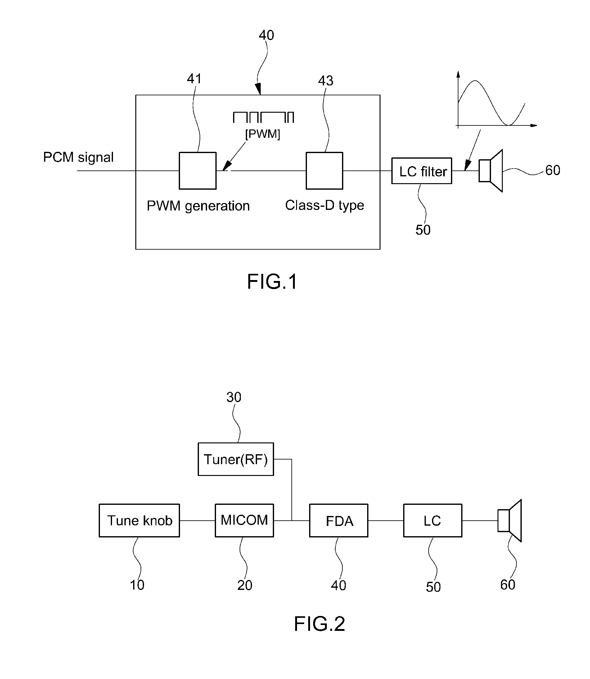
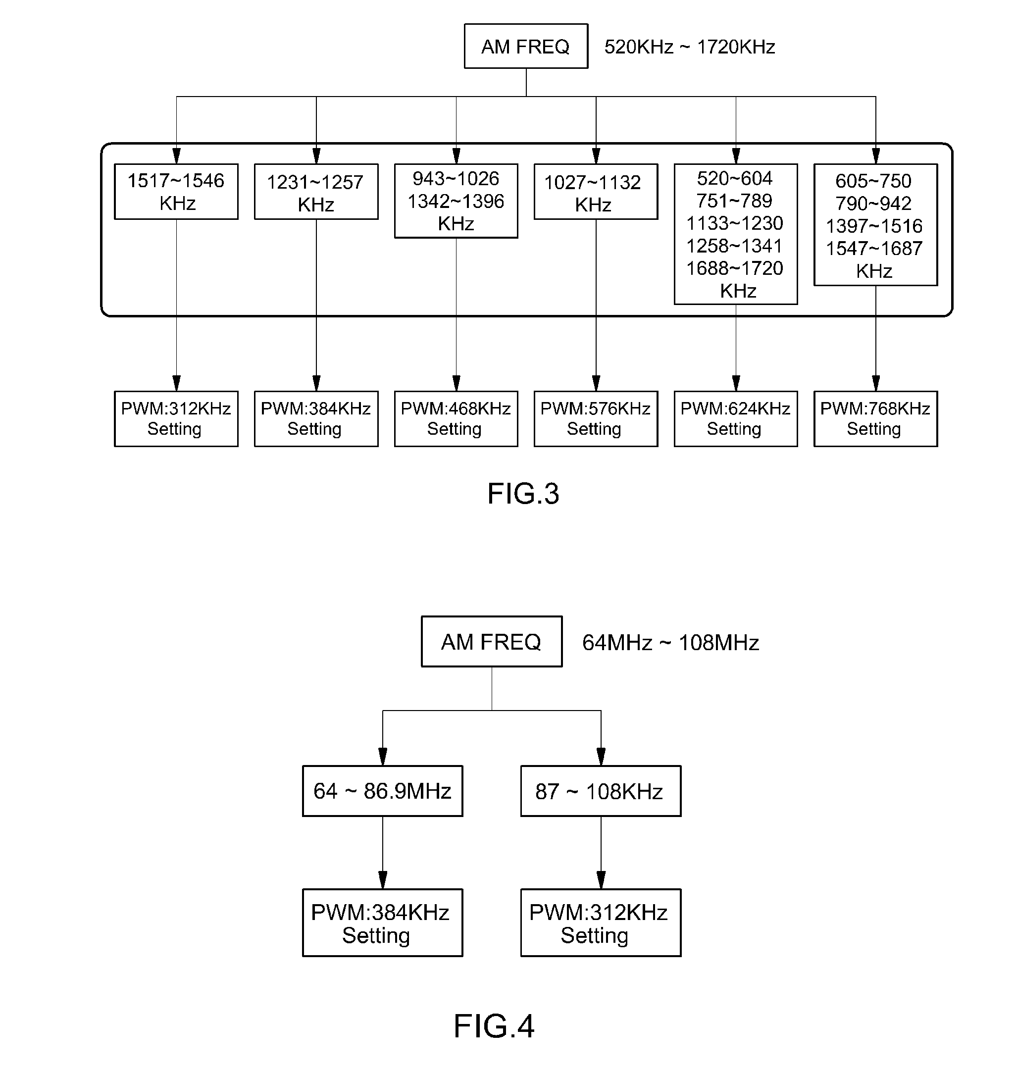
A vehicle audio system includes: a tune knob configured to select a frequency of a desired radio broadcast; a microcomputer configured to detect a broadcast frequency input through the tune knob and to determine an optimal sampling frequency of a full digital amplifier based on the detected broadcast frequency; a tuner configured to receive only a broadcast signal corresponding to the frequency selected through the tune knob; and the full digital amplifier configured to generate a digital signal by sampling the broadcast signal received by the tuner at the optimal sampling frequency determined by the microcomputer and to amplify and output the generated digital signal.

Description

CROSS-REFERENCE TO RELATED APPLICATION[0001]This application claims under 35 U.S.C. §119(a) the benefit of and priority to Korean Patent Application No. 10-2014-0068096 filed on Jun. 5, 2014, the entire contents of which are incorporated herein by reference.BACKGROUND[0002]1. (a) Technical Field[0003]The present disclosure relates to a vehicle audio system and a noise removal method thereof, and more particularly, to a vehicle audio system and a noise removal method thereof, which can efficiently remove noise that may be generated in a vehicle audio system employing a full digital amplifier.[0004]2. (b) Background Art[0005]In general, a vehicle audio system enables listeners to listen to the radio, as well as various sound sources stored in analog form using an external media device (e.g., CD, MP3, etc.). An ordinary vehicle audio system typically uses an amplifier for amplifying audio signals and a speaker for outputting audio signals to provide sounds to the driver and passengers....

Claims


Application Information

Patent Timeline
IPC IPC(8): G10K11/175H03F3/181
CPCH03F3/181G10K11/175H03F3/217H03F2200/321H03F2200/351
Inventor HWANG, SEUNG HAIGO, JI SUNKIM, YOUNG
Owner HYUNDAI MOTOR CO LTD
Learn More