Reactor provided with a cooler

a technology of a cooler and a reactor, which is applied in the direction of fixed inductance, basic electric elements, inductance, etc., can solve the problem of large heat generated by current, and achieve the effect of improving the cooling

Active Publication Date: 2015-12-10
TOYOTA JIDOSHA KK
View PDF2 Cites 12 Cited by
  • Summary
  • Abstract
  • Description
  • Claims
  • Application Information

AI Technical Summary

Benefits of technology

[0007]The present invention provides a reactor provided with a cooler, which offers a better cooling effect.
[0008]The reactor provided with a cooler in accordance with a one aspect of the present invention, comprising: a coil; a core formed of a soft magnetic material, the core covers an inside of the coil and an outer periphery of the coil; the cooler being arranged on both sides of the core, the core and the cooler being pressed in a stacking direction of the core and the cooler; a thickness of the core in the stacking direction being smaller than a length of a height of a surface of the core that faces the stacking direction, and the thickness of the core in the stacking direction being smaller than a length of a width of the surface of the core that faces the stacking direction. With the reactor described in this aspect, the core is a flat body in which a thickness in the stacking direction is smaller than a length of a height of a surface of the core that faces the stacking direction, and is smaller than a length of a width of the surface facing the stacking direction described above. By making the thickness of the core in the stacking direction thin as described above, heat from the center portion of the coil is quickly transferred to the adjacent cooler on both sides. A stacked body of the core and the cooler are pressed in a stacking direction. Pressing in the stacking direction brings the core and the cooler into closer contact, and thereby increases the heat transfer efficiency from the core to the cooler.
[0009]Also, using a core that covers the inside and the outer periphery of the coil enables large inductance to be ensured, compared with a reactor having a core arranged only on the inside of the coil. This is because magnetic flux also passes on the outer periphery of the core. This kind of a core may be manufactured by hardening soft magnetic particles (or powder). This kind of a core is may typically be made by injection molding resin that includes soft magnetic particles.

Problems solved by technology

A device with a large allowable current generates a large amount of heat.

Method used


Image

  • Reactor provided with a cooler
  • Reactor provided with a cooler
  • Reactor provided with a cooler

Examples


first embodiment

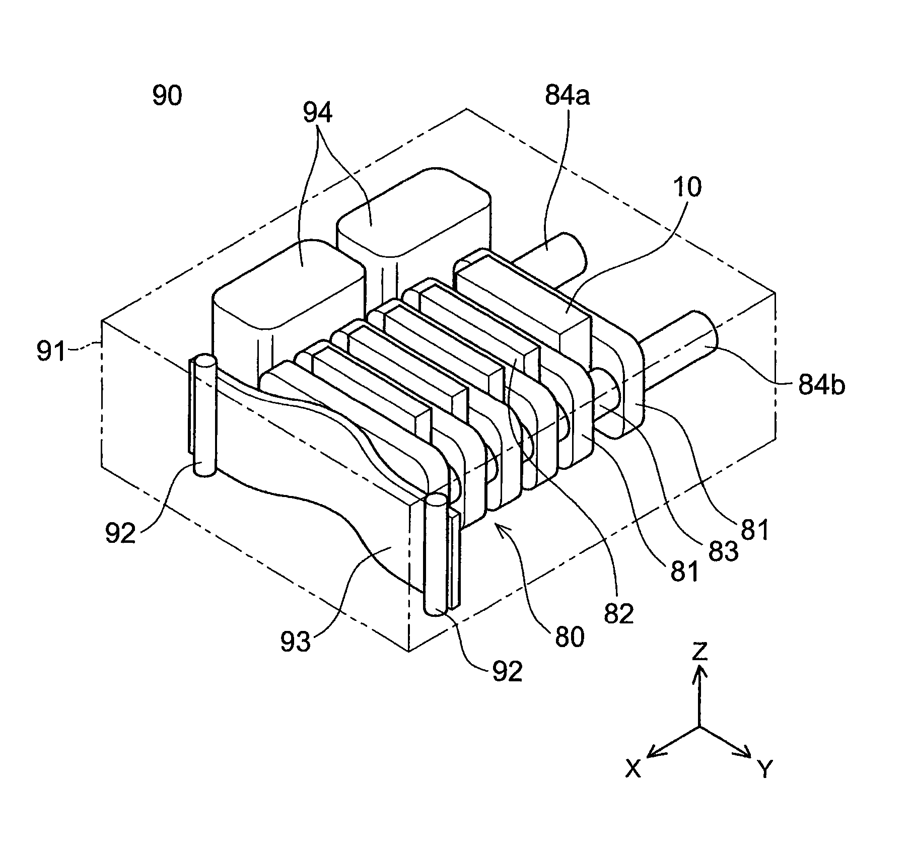
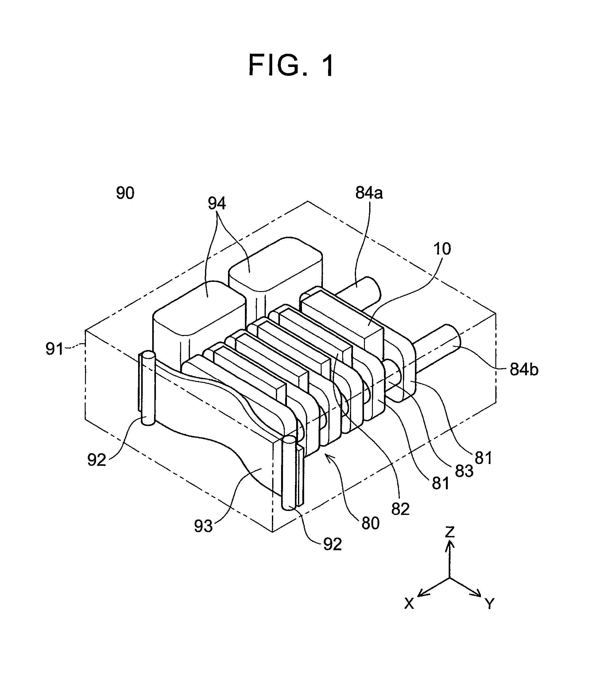
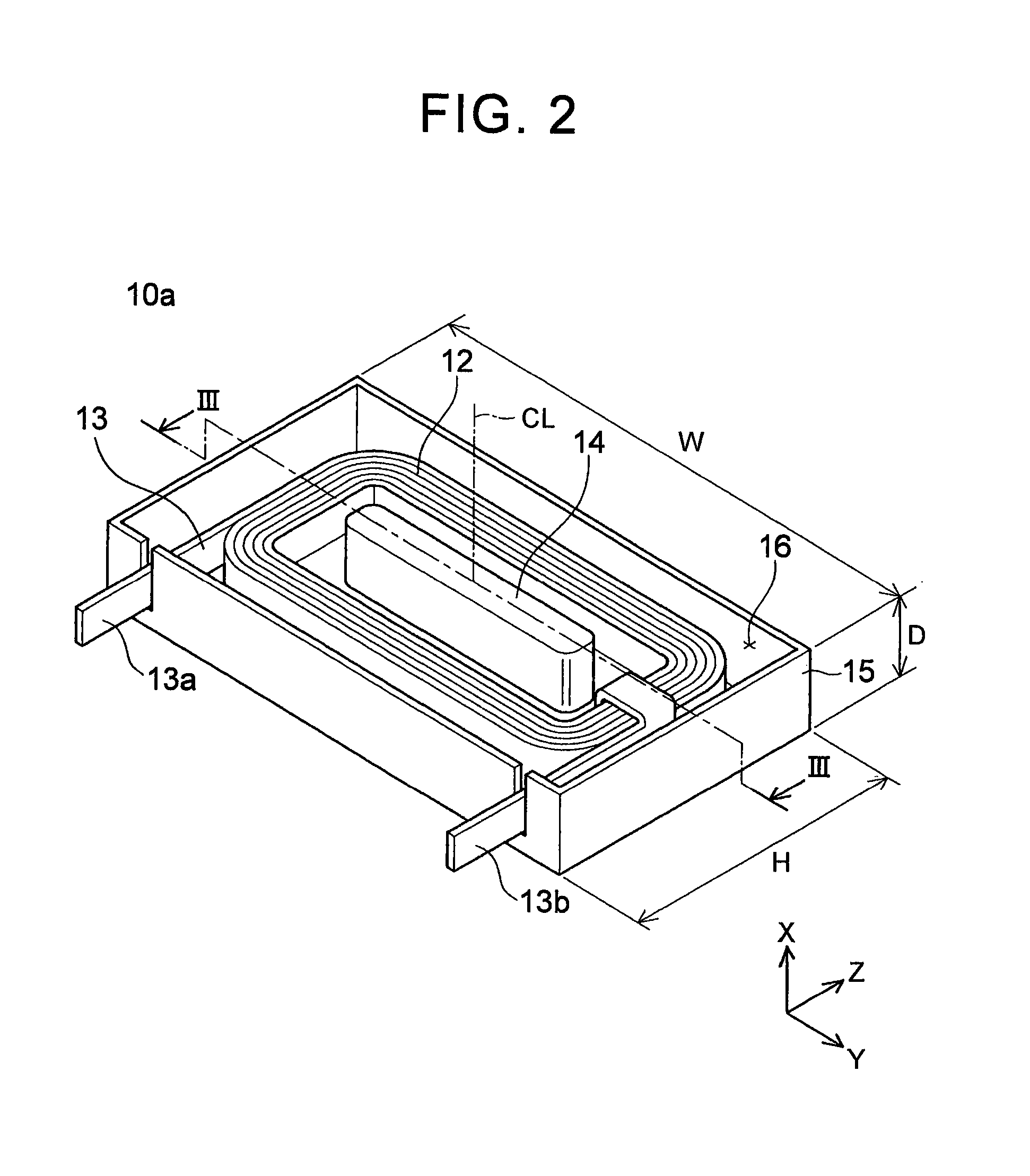
[0029]Next, a first embodiment of the reactor 10 described above will be described. FIG. 2 is a perspective view of a reactor 10a according to the first embodiment of the present invention. The main component of the reactor 10a is a coil 12 of wound flat wire 13. An inside and outer periphery of the coil 12 are molded with resin that includes soft magnetic particles, but in FIG. 1, the resin mold is not shown in order to shown the shape of the coil. In FIG. 2, resin (i.e., resin that includes soft magnetic particles) is filled into a space denoted by reference character 16. This resin mold corresponds to a core of the reactor. Therefore, for the sake of simplicity, the core 16 will be represented by the reference character 16 that indicates the space. In other words, the core 16 is formed of hardened soft magnetic particles. Also, a magnetic shielding plate is arranged on both sides of the coil 12 in the coil axial direction, but is not shown in the drawings. The magnetic shielding ...

second embodiment

[0038]Next, a reactor 10b according to a second embodiment of the present invention will be described. FIG. 4 is a perspective view of the reactor 10b. FIG. 5 is a sectional view taken along line V-V in FIG. 4. The reactor 10b is the same size as the reactor 10a in the first embodiment. The reactor 10b is also a flat body in which the thickness in the stacking direction is smaller than the length of the height and the length of the width of a surface facing the stacking direction. In FIGS. 4 and 5 as well, similar to FIGS. 2 and 3, the core is not shown, but the space denoted by reference character 16 corresponds to the core 16. Hereinafter as well, for the sake of simplicity, the space denoted by reference character 16 will represent the core 16.

[0039]The reactor 10b includes two consecutive coil portions 112a and 112b that are connected together in series. Each of these coil portions is a flatwise coil. The two consecutive coil portions 112a, 112b are arranged lined up in a direct...

third embodiment

[0044]Next, a reactor 10c of a third embodiment of the present invention will be described. FIG. 6 is a perspective view of the reactor 10c. In FIG. 6 as well, the core is not shown in order to better show the coils. In FIG. 6, the space indicated by reference character 16 is normally filled up by the core 16.

[0045]The reactor 10c is also the same size as the reactor 10a of the first embodiment. The reactor 10c is also a flat body in which the thickness in the stacking direction is less than the length of the height and the length of the width of a surface facing the stacking direction.

[0046]The reactor 10c employs an edgewise coil. Edgewise refers to winding such that a flat surface of a flat wire faces the coil axial direction, and the flat surface overlaps with itself. In other words, with an edgewise winding, the stacking direction of the flat wire follows the coil axis.

[0047]The reactor 10c includes two consecutive coil portions 212a and 212b that are connected together in seri...


PUM

PropertyMeasurementUnit
soft magneticaaaaaaaaaa
thicknessaaaaaaaaaa
lengthaaaaaaaaaa

Abstract

A reactor provided with a cooler, comprising: a coil, a core formed of a soft magnetic material, the core covers an inside of the coil and an outer periphery of the coil; the cooler being arranged on both sides of the core, the core and the cooler being pressed in a stacking direction of the core and the cooler; a thickness of the core in the stacking direction being smaller than a length of a height of a surface of the core that faces the stacking direction; and the thickness of the core in the stacking direction being smaller than a length of a width of the surface of the core that faces the stacking direction.

Description

BACKGROUND OF THE INVENTION[0001]1. Field of the Invention[0002]The invention relates to a reactor provided with a cooler. The reactor is a passive element that uses a coil, and may also be referred to as an “inductor”.[0003]2. Description of Related Art[0004]Electric vehicles including hybrid vehicles are equipped with a power converter that converts output power of a battery to power suitable for driving a running motor. The power converter may include not only an inverter circuit that converts direct current into alternating current, but also a voltage converter circuit. A power converter for an electric vehicle handles large current, so devices with a large allowable current are also employed for the devices used for the inverter circuit and the voltage converter circuit.[0005]A device with a large allowable current generates a large amount of heat. One device that generates a particularly large amount of heat is a reactor that is included in a voltage converter circuit. Therefo...

Claims


Application Information

Patent Timeline
Patent Type & Authority Applications(United States)
IPC IPC(8): H01F27/10H01F27/26H01F27/28H01F27/255
CPCH01F27/10H01F27/255H01F27/288H01F27/2823H01F27/263H01F27/16H01F27/22H01F37/00H01F27/02H01F27/08H01F27/06
Inventor NOBUSAKA, MAOATSUMI, TAKASHI
Owner TOYOTA JIDOSHA KK
Why Eureka
Try Eureka