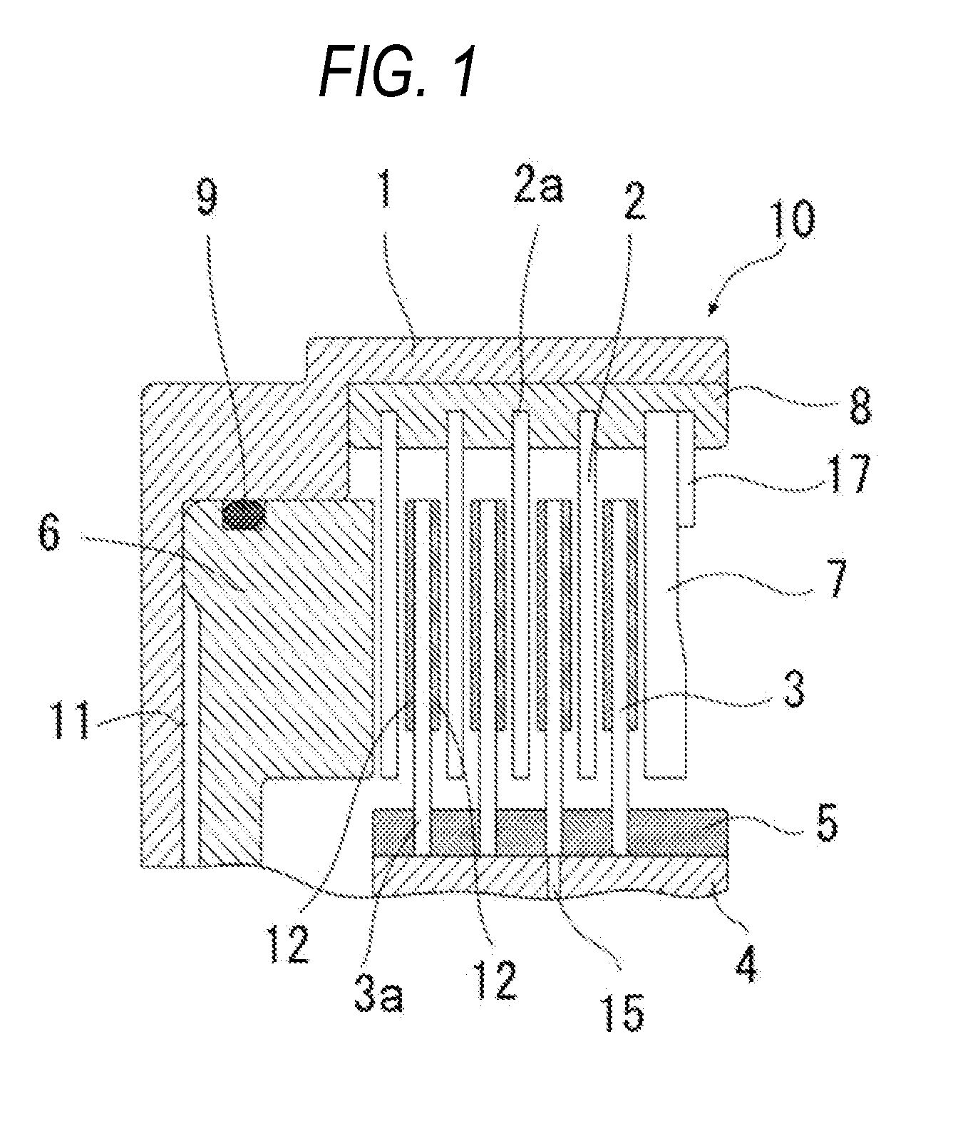
Friction plate and wet multiple-plate clutch with friction plate
a technology of friction plate and friction plate, which is applied in the direction of fluid-actuated clutches, non-mechanical actuated clutches, clutches, etc., can solve the problems of increasing the friction member of the friction plate of the wet multiple-plate clutch increasing the friction plate friction plate, etc., to improve the performance of cooling friction members and improve the oil draining performance
- Summary
- Abstract
- Description
- Claims
- Application Information
AI Technical Summary
Benefits of technology
Problems solved by technology
Method used
Image
Examples
first embodiment
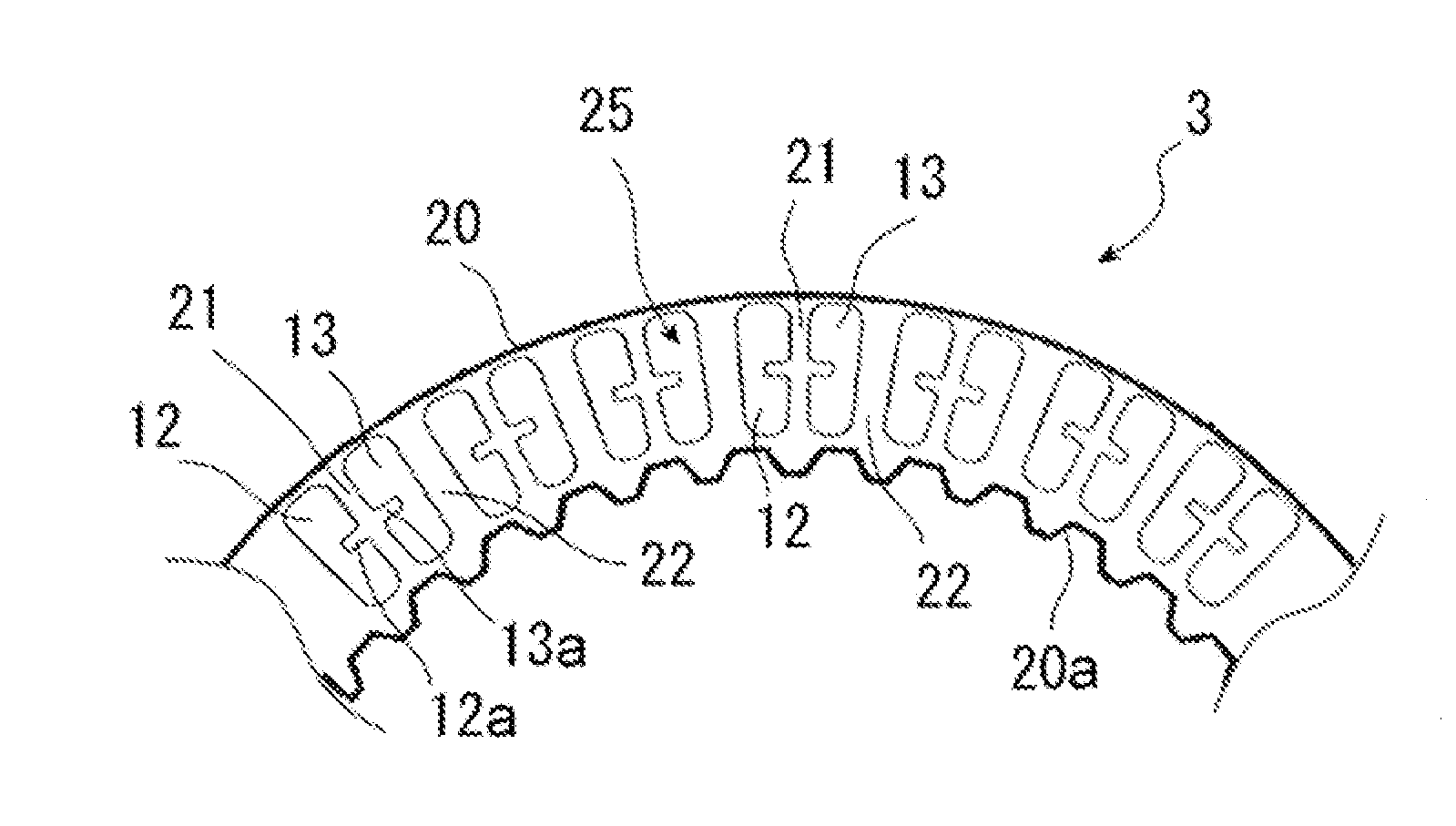
[0041]FIG. 2 is a partial front view of a friction plate 3, which illustrates a first embodiment of the present invention. The friction plate 3 has a friction surface 25 formed by circularly fixing friction material segments 12 and 13 to a substantially annular core plate 20 by an adhesive agent or the like. The core plate 20 has, on the inner periphery thereof, a spline 20a that engages with a spline 5 of a hub 4.
[0042]As illustrated in FIG. 2, each of the friction plates 3 has pairs of the friction material segments 12 and 13 circularly arranged. Through grooves 21 and 22, which penetrate from the inside diameter side to the outside diameter side of the core plate 20 and radially extend, are formed between the friction material segments 12 and 13.
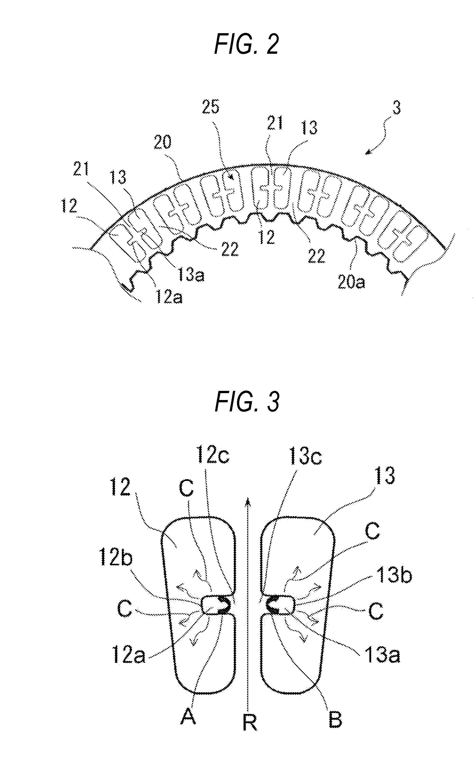
[0043]The friction material segments 12 and 13 have circumferential grooves 12a and 13a, respectively, which open to the through groove 21, extend in the circumferential direction, and end in the friction material segments. The circumfere...
second embodiment
[0055]FIG. 4 is a front view of friction material segments illustrating a second embodiment of the present invention. Paired friction material segments 32 and 33 have the same shape. The friction material segment 32 is provided with circumferential grooves 32a at both end portions in the circumferential direction. Similarly, the friction material segment 33 is provided with circumferential grooves 33a at both end portions in the circumferential direction. In the present embodiment, a single friction material segment is provided with two circumferential grooves formed in alignment in the radial direction. The circumferential grooves 32a and 33a are provided substantially at the middle in the radial direction of the friction material segments. The circumferential grooves 32a and 33a are symmetrically provided relative to a through groove 21.
[0056]According to the second embodiment, the oil that flows through all of the through grooves 21, each of which lies between the friction materi...
third embodiment
[0057]FIG. 5 is a front view of friction material segments illustrating a third embodiment of the present invention. Paired friction material segments 42 and 43 have the same shape. The friction material segment 42 has a circumferential groove 42a at one end portion in the circumferential direction. Similarly, the friction material segment 43 has a circumferential groove 43a at one end portion in the circumferential direction. As illustrated in FIG. 5, the circumferential groove 42a and the circumferential groove 43a open in the same direction. The circumferential grooves 42a and 43a are provided substantially at the middle in the radial direction of the friction material segments. However, the circumferential grooves 42a and 43a are provided asymmetrically with respect to a through groove 21.
[0058]According to the third embodiment, as with the second embodiment, the oil that flows through all of the through grooves 21, each of which lies between the friction material segment 42 and...
PUM
 Abstract
Description
Claims
Application Information
 - R&D
- Intellectual Property
- Life Sciences
- Materials
- Tech Scout
- Unparalleled Data Quality
- Higher Quality Content
- 60% Fewer Hallucinations
Browse by: Latest US Patents, China's latest patents, Technical Efficacy Thesaurus, Application Domain, Technology Topic, Popular Technical Reports.
© 2025 PatSnap. All rights reserved.Legal|Privacy policy|Modern Slavery Act Transparency Statement|Sitemap|About US| Contact US: help@patsnap.com


