Wide-Angle Projection Lens

a projection lens and wide-angle technology, applied in the field of wide-angle projection lenses, can solve the problems of unsuitable projection lenses for projectors, the light flux of led light sources is apparently smaller than the traditional high-pressure mercury-vapor lamps, etc., and achieve good optical performance and resolution.

Active Publication Date: 2015-12-17
SINTAI OPTICAL SHENZHEN CO LTD +1
View PDF5 Cites 9 Cited by
  • Summary
  • Abstract
  • Description
  • Claims
  • Application Information

AI Technical Summary

Benefits of technology

[0005]The invention provides a wide-angle projection lens to solve the above problems. The wide-angle projection lens is provided with characteristics of a smaller F-number, a larger angle of view and miniaturization, and still has good optical performance and resolution.

Problems solved by technology

However, the light flux of an LED light source is apparently smaller than the traditional high pressure mercury-vapor lamp.
According, this kind of projection lens is unsuitable for projectors which adopt LED as a light source.

Method used


Image

  • Wide-Angle Projection Lens
  • Wide-Angle Projection Lens
  • Wide-Angle Projection Lens

Examples


first embodiment

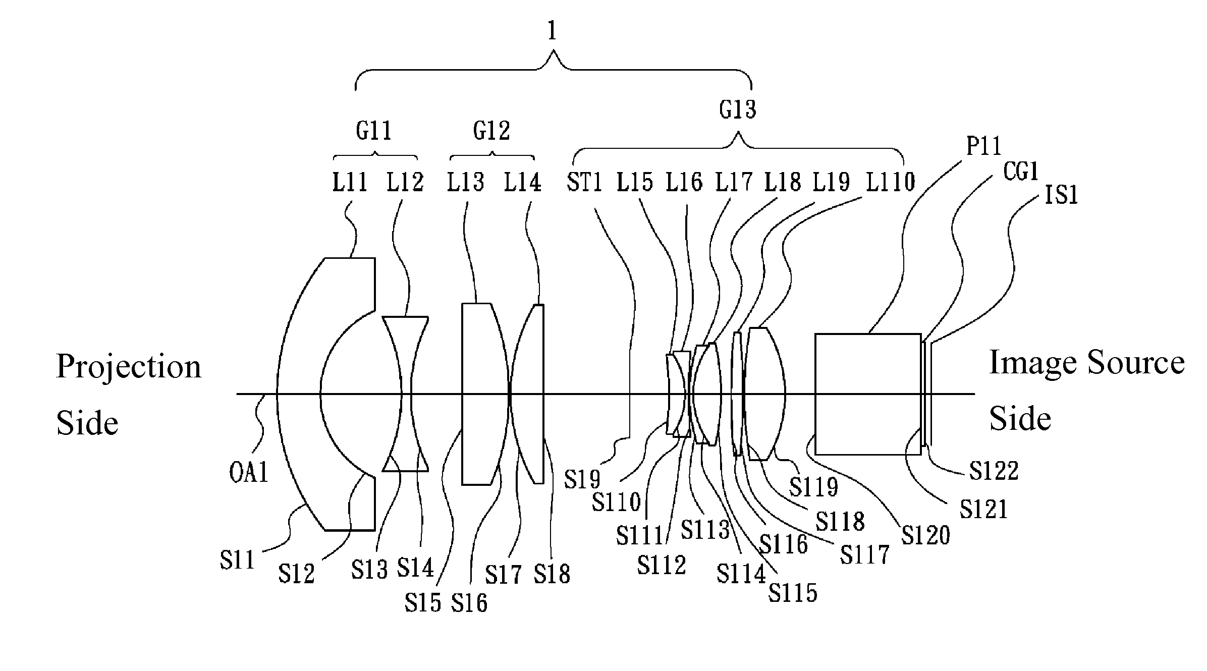
[0032]Referring to FIG. 1, FIG. 1 is a lens layout diagram of a wide-angle projection lens in accordance with the invention. The wide-angle projection lens 1 includes a first lens group G11, a second lens group G12 and a third lens group G13, all of which are arranged in order from a projection side to an image source side along an optical axis OA1. In operation, light rays from an image source IS1 are projected on the projection side. The first lens group G11 is with negative refractive power and includes a first lens L11 and a second lens L12, all of which are arranged in order from the projection side to the image source side along the optical axis OA1. The first lens L11 is a convex-concave lens made of plastic material and includes a convex surface S11 facing the projection side and a concave surface S12 facing the image source side, wherein both of the convex surface S11 and concave surface S12 are aspheric surfaces. The second lens L12 is a biconcave lens made of glass materi...

second embodiment

[0045]Referring to FIG. 3, FIG. 3 is a lens layout diagram of a wide-angle projection lens in accordance with the invention. The wide-angle projection lens 2 includes a first lens group G21, a second lens group G22 and a third lens group G23, all of which are arranged in order from a projection side to an image source side along an optical axis OA2. In operation, light rays from an image source IS2 are projected on the projection side. The first lens group G21 is with negative refractive power and includes a first lens L21 and a second lens L22, all of which are arranged in order from the projection side to the image source side along the optical axis OA2. The first lens L21 is a convex-concave lens made of plastic material and includes a convex surface S21 facing the projection side and a concave surface S22 facing the image source side, wherein both of the convex surface S21 and concave surface S22 are aspheric surfaces. The second lens L22 is a biconcave lens made of glass materi...


PUM


Abstract

A wide-angle projection lens includes a first lens group with negative refractive power, a second lens group with positive refractive power and a third lens group with positive refractive power, all of which are arranged in order from a projection side to an image source side along an optical axis. The third lens group includes a first lens, a second lens, a third lens, a fourth lens, a fifth lens and a sixth lens, all of which are arranged in order from the projection side to the image source side along the optical axis, wherein the third lens and the fourth lens are cemented together to form a cemented lens and there is no air gap between the third lens and the fourth lens.

Description

BACKGROUND OF THE INVENTION[0001]1. Field of the Invention[0002]The present invention relates to a wide-angle projection lens.[0003]2. Description of the Related Art[0004]Projectors which adopt LED as a light source have the advantage of small size. However, the light flux of an LED light source is apparently smaller than the traditional high pressure mercury-vapor lamp. So projectors which use an LED light source need to adopt a lens with larger aperture, that is a lens with smaller F-number. Generally, projectors which use high pressure mercury-vapor lamp have a projection lens with smaller aperture, where the F-number is generally larger than 2.4. According, this kind of projection lens is unsuitable for projectors which adopt LED as a light source. On the other hand, for projecting a larger scene within a short projecting length, a short-focus lens, which is a wide-angle lens, is needed. For the two aforementioned reasons, there is a need for a new projection lens with small F-n...

Claims


Application Information

Patent Timeline
Patent Type & Authority Applications(United States)
IPC IPC(8): G02B13/16G02B9/64G02B13/18
CPCG02B13/16G02B9/64G02B13/18G02B13/04
Inventor LEE, TSAN-HAW
Owner SINTAI OPTICAL SHENZHEN CO LTD
Why Eureka
Try Eureka