Optical acquisition device for biometric systems

a biometric system and optical acquisition technology, applied in the field of optical acquisition in biometric systems, can solve the problems of affecting the quality of the image, so as to eliminate the disadvantages and not bulky

Active Publication Date: 2015-12-17
IDEMIA IDENTITY & SECURITY FRANCE
View PDF8 Cites 3 Cited by
  • Summary
  • Abstract
  • Description
  • Claims
  • Application Information

AI Technical Summary

Benefits of technology

[0015]An aim of the invention is to eliminate the disadvantages of techniques used to date for determining a distance from the object in the case of biometric systems.
[0016]More precisely, the invention proposes a solution which is inexpensive and not bulky.

Problems solved by technology

This method is highly efficacious but has the disadvantage of being fairly bulky and disrupting the resulting image by the presence of the sight.
It is further costly in terms of additional optics and electronics.
The disadvantage of the coded apertures however is that they strongly degrade the quality of the image they produce.
They are consequently generally considered incompatible with highly precise acquisition of images.

Method used


Image

  • Optical acquisition device for biometric systems
  • Optical acquisition device for biometric systems

Examples


Embodiment Construction

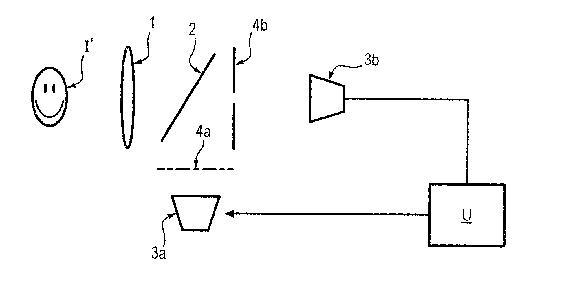
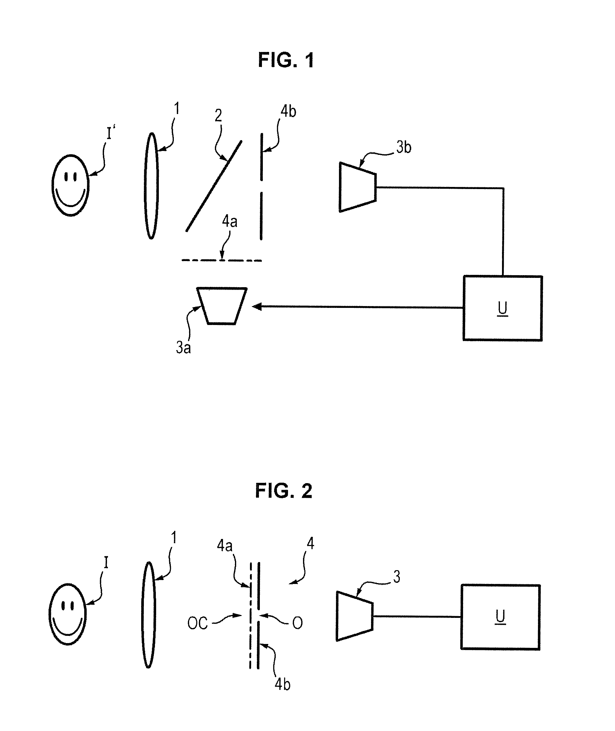
[0051]In the example illustrated in FIG. 1, the device is intended to acquire an image of the face or iris of the eye of an individual (object I) passing in front of said device.

[0052]Of course, it would be used in the same way as for other biometric applications needing “OTF” acquisitions (acquisition “on the fly” images of veins and or fingerprints, for example).

[0053]The device comprises an optic 1 and a beam splitter 2 and two imagers or cameras 3a, 3b oriented at 90° one relative to the other and to which the images separated by the beam splitter 2 are sent back.

[0054]The camera 3a is linked to a diaphragm 4a with coded aperture interposed between said camera and the beam splitter 2, while the camera 3b is linked to a classic centred and circular diaphragm 4b, interposed between said camera 3b and the beam splitter 2.

[0055]The beam splitter 2 is for example a beam splitter which filters colours by transmitting images in different frequency bands to camera 3a and camera 3b.

[005...


PUM


Abstract

The invention relates to a device for acquisition of images for a biometric system, which includes an optical assembly and at least one imager for acquisition of an image of an object to be analysed presented in front of the assembly at a non-determined distance from the latter. The assembly includes at least one diaphragm with a coded aperture. The optical assembly allows acquisition by the sensor(s) of an image of the object capable of being exploited to deduce therefrom the searched biometric information, and of an image of the object acquired via the coded aperture of the diaphragm. The device also includes a processing unit to determine the distance of the object to be analysed as a function of the image of the object acquired via the coded aperture of the diaphragm.

Description

GENERAL TECHNICAL FIELD AND PRIOR ART[0001]The present invention relates to .optical acquisition in biometric systems.[0002]It applies particularly advantageously to biometric systems using acquisition of images on the fly (“OTF” or “On The Fly” as per English terminology in general use), for example for identification or authentication by facial recognition, iris acquisition, fingerprint acquisition or venous image acquisition, etc. Biometric systems conventionally endeavour to know the distance separating the object from the camera, which enables:[0003]deconvoluting with appropriate deconvolution filter, and therefore canceling blurring;[0004]activating focusing systems,[0005]knowing the resolution at which the object is being observed.[0006]The knowledge of this distance is often obtained by projection of a sight and by triangulation between the latter and the sight lines occurring with formation of images. This method is highly efficacious but has the disadvantage of being fairl...

Claims


Application Information

Patent Timeline
Patent Type & Authority Applications(United States)
IPC IPC(8): H04N5/232H04N5/225G06K9/00G06T7/00
CPCH04N5/23219G06T7/0051H04N5/2254G06T2207/30196G06K9/00255G06K9/00604G06K9/00013H04N5/23212A61B3/14A61B5/117G06T7/50G06V40/18H04N23/61A61B5/1171H04N23/611
Inventor RIEUL, FRANCOISPICARD, SYLVAINE
Owner IDEMIA IDENTITY & SECURITY FRANCE
Why Eureka
Try Eureka