Slot-Coupled CW Standing Wave Accelerating Cavity

Active Publication Date: 2015-12-17
JEFFERSON SCI ASSOCS LLC
View PDF23 Cites 10 Cited by
  • Summary
  • Abstract
  • Description
  • Claims
  • Application Information

AI Technical Summary

Benefits of technology

[0008]It is therefore an object of the present invention to provide a more compact and simpler accelerator arrangement for a particle accelerator.
[0009]A further object of the invention is to provide a method for increasing the electron capture efficiency a particle accelerator.
[0010]Another object of the invention is to provide an accelerator arrangement that reduces the amount of input power required to drive the accelerator for a given output energy.
[0011]A further object is to provide an accelerator arrangement for Continuous Wave (CW) and high duty-factor accelerators that significantly reduces the input power and cooling requirements.
[0012]A further object of the invention is to provide cavities with internal slots that are symmetrical with respect to the cavity center axis and which do not introduce any transverse kicks to the accelerating beam and allow higher current operati

Problems solved by technology

The slot-coupling method ma

Method used


Image

  • Slot-Coupled CW Standing Wave Accelerating Cavity
  • Slot-Coupled CW Standing Wave Accelerating Cavity
  • Slot-Coupled CW Standing Wave Accelerating Cavity

Examples


Embodiment Construction

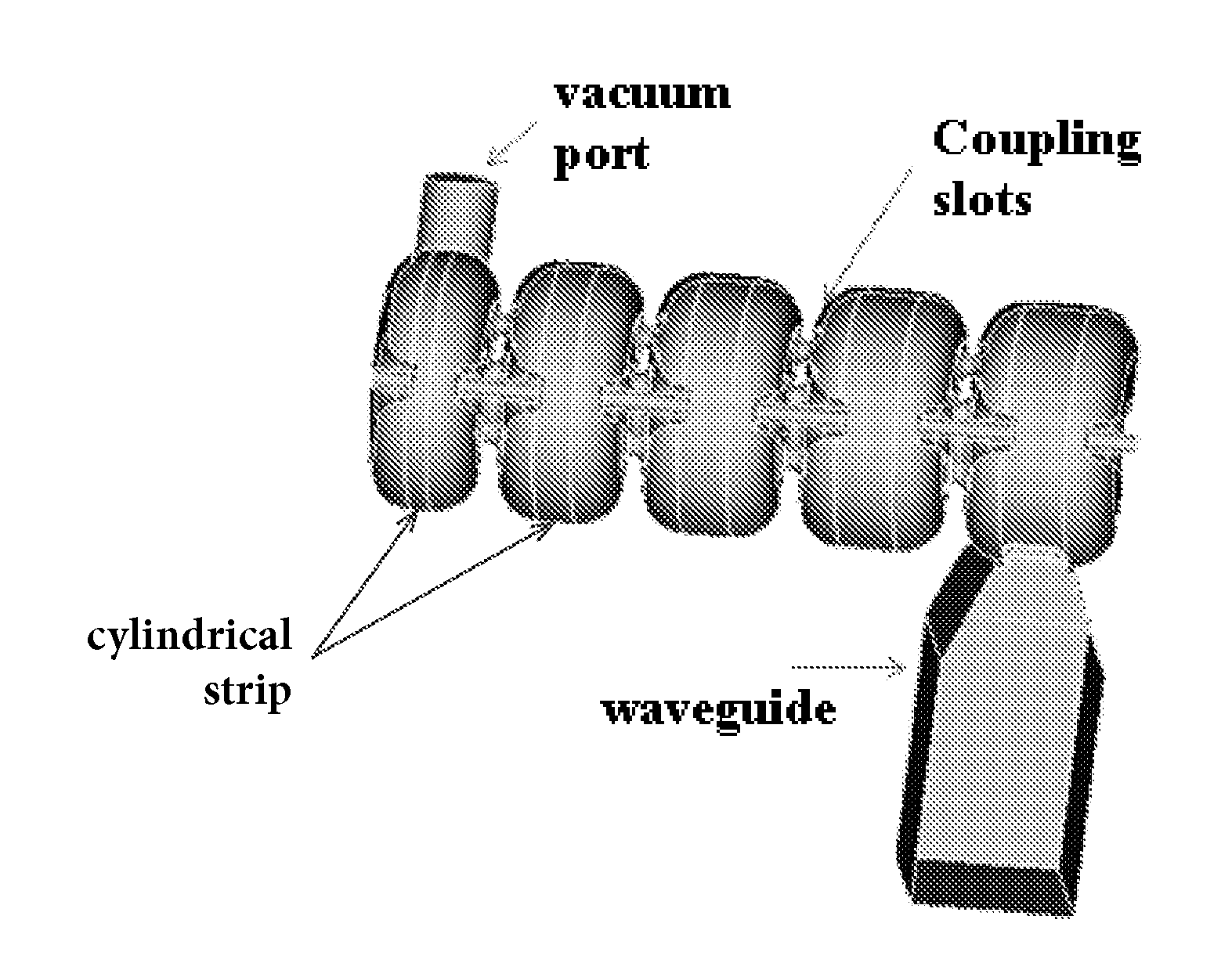
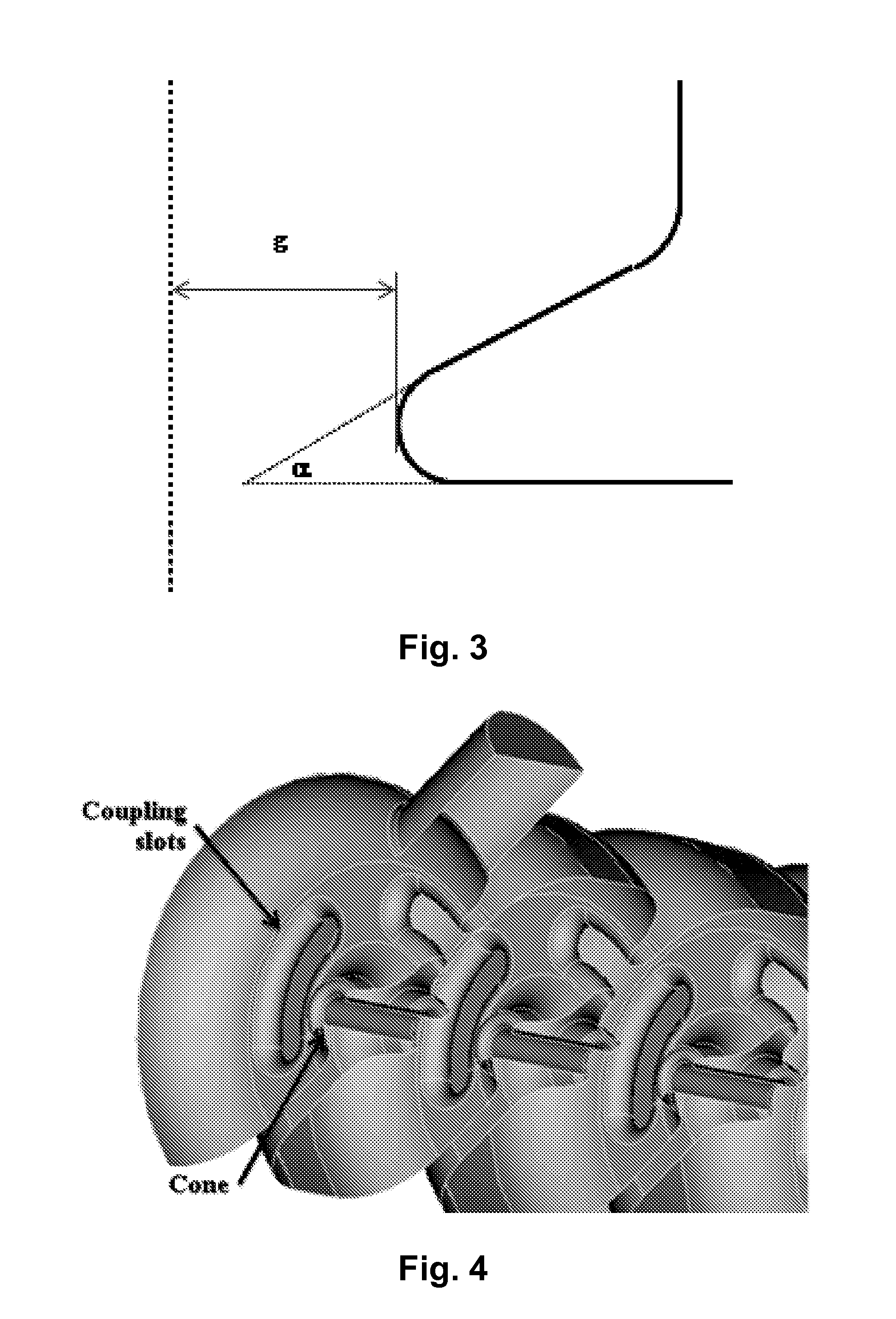
[0027]The present invention is a compact, efficient CW standing wave accelerating cavity. This is a multi-cell cavity that can be used for graded beta acceleration with different cell designs, or for beta equal to 1 acceleration with the same cell design for each single cell. The coupling between cells is realized with a plurality of kidney-shaped slots on the wall between cells. The slot-coupling method makes the design very compact. The shape of the cell, including the slots and the cone, are optimized to maximize the power efficiency and minimize the peak power density on the surface.

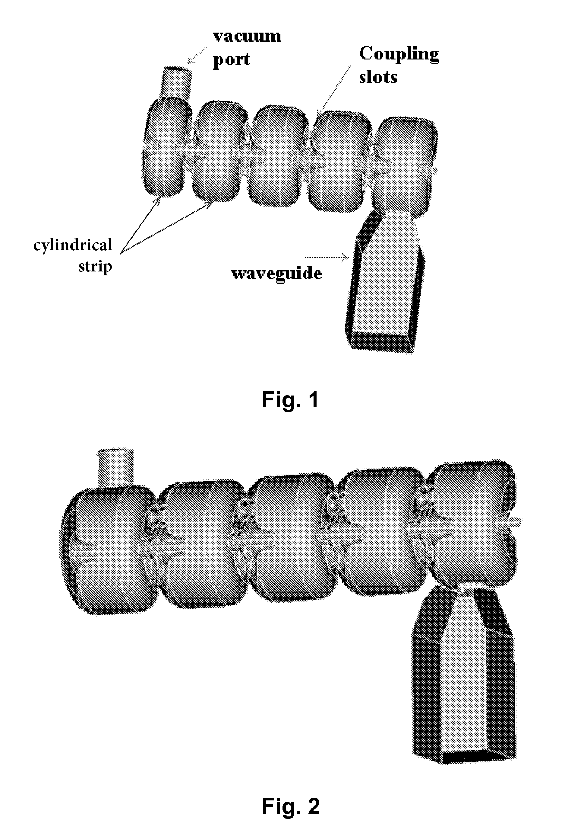
[0028]Referring to FIG. 1, there is shown the preferred embodiment of a cavity design for graded beta acceleration. The preferred embodiment includes three of the slots. With a 7 kW power supply, 3 MV / m electric fields are produced, and electrons can be accelerated from beta=0.6 to 0.9. After that, electrons may be accelerated with a high beta cavity as shown FIG. 2 for further acceleration. The oute...


PUM


Abstract

A slot-coupled CW standing wave multi-cell accelerating cavity. To achieve high efficiency graded beta acceleration, each cell in the multi-cell cavity may include different cell lengths. Alternatively, to achieve high efficiency with acceleration for particles with beta equal to 1, each cell in the multi-cell cavity may include the same cell design. Coupling between the cells is achieved with a plurality of axially aligned kidney-shaped slots on the wall between cells. The slot-coupling method makes the design very compact. The shape of the cell, including the slots and the cone, are optimized to maximize the power efficiency and minimize the peak power density on the surface. The slots are non-resonant, thereby enabling shorter slots and less power loss.

Description

CROSS-REFERENCE TO RELATED APPLICATIONS[0001]This application claims the priority of Provisional U.S. Patent Application Ser. No. 62 / 011,920 filed Jun. 13, 2014.GOVERNMENT LICENSE RIGHTS[0002]This invention was made with government support under Management and Operating Contract No. DE-ACO5-060R23177 awarded by the Department of Energy. The United States Government has certain rights in the invention.FIELD OF THE INVENTION[0003]The present invention relates to particle accelerator structures and more particularly to a continuous wave (CW) multi-cell accelerating cavity.BACKGROUND OF THE INVENTION[0004]The side-coupling arrangement used in conventional accelerator cavities results in a large and complex assembly. Injectors using cavities of this type combined with thermionic cathodes typically exhibit an electron capture efficiency of less than 40%.[0005]In order to reduce the performance limitations of side-coupled cavities, resonant coupling slots have been proposed in multi-cell a...

Claims


Application Information

Patent Timeline
IPC IPC(8): H05H11/00H05H7/00
CPCH05H7/00H05H11/00H05H9/044H05H7/18H05H7/22H05H2007/225
Inventor WANG, SHAOHENGRIMMER, ROBERTWANG, HAIPENG
Owner JEFFERSON SCI ASSOCS LLC
Why Eureka
Try Eureka