Noise-reducing shielded cable
- Summary
- Abstract
- Description
- Claims
- Application Information
AI Technical Summary
Benefits of technology
Problems solved by technology
Method used
Image

Examples
embodiment 1
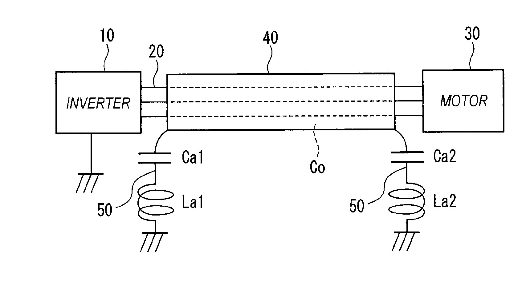
[0050]As shown in FIG. 1, a three-phase output from an inverter 10 is sent to a motor 30 through a cable 20. Three cables of the cable 20 between the inverter 10 and the motor 30 are covered with a shield layer 40.
[0051]The noise-reducing shielded cable according to Embodiment 1 is characterized in that a series circuit of a capacitor Ca1 and an inductor La1 is inserted in a ground wire 50 grounding one end of the shield layer 40, and a series circuit of a capacitor Ca2 and an inductor La2 is inserted in a ground wire 50 grounding the other end of the shield layer 40.
[0052]40>
[0053]The shield layer 40 includes three core wires through which a signal is transmitted, and a shield layer that surrounds the three core wires. The shield layer 40 is characterized in that capacitance C0 is provided between the core wires and the shield layer. As is understood from FIG. 1, a rigorous shield structure as shown in FIG. 8 does not have to be used between the inverter 10 and the shield layer 40 ...
embodiment 2
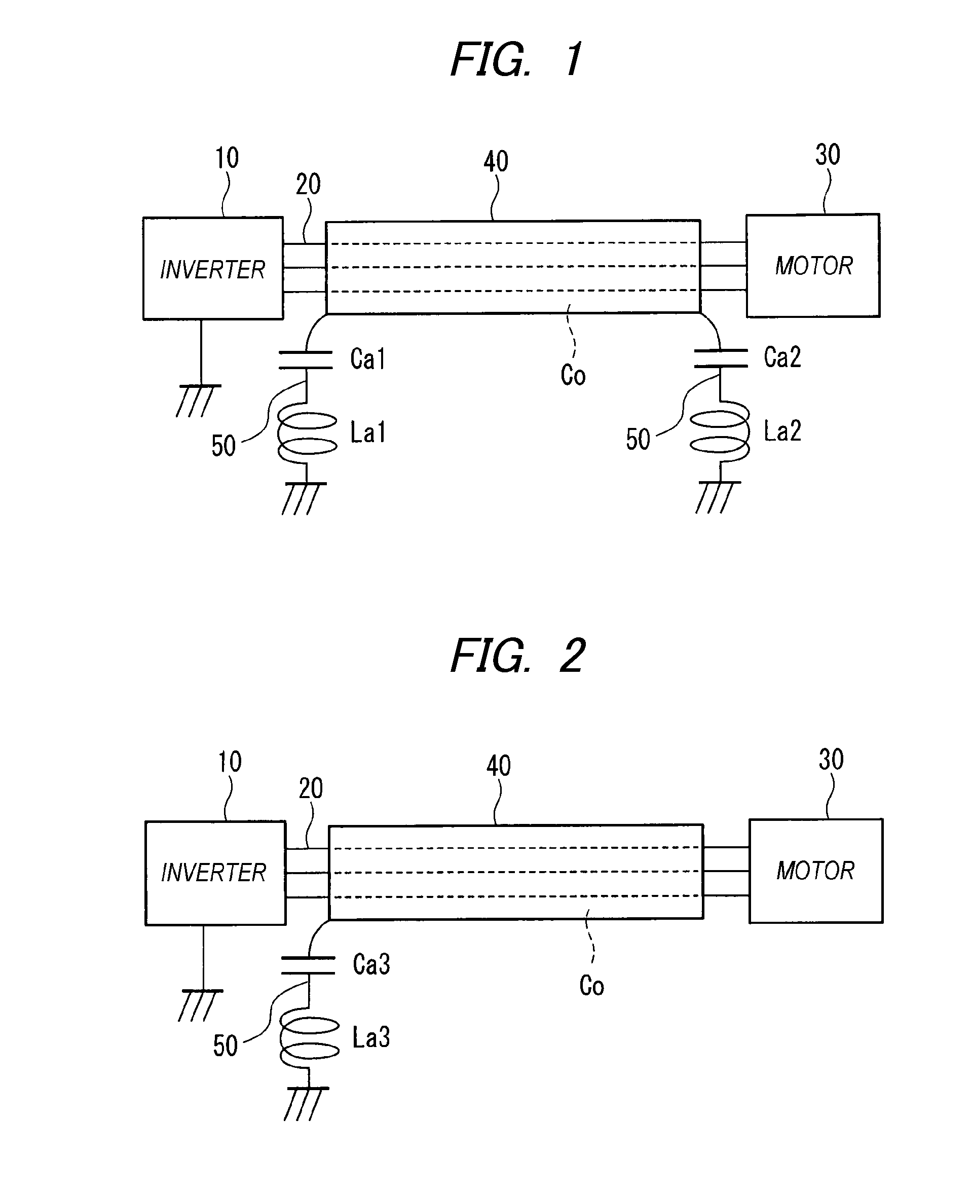
[0064]FIG. 2 is a block diagram of a noise-reducing shielded cable according to Embodiment 2 of the invention.
[0065]In FIG. 2, a three-phase output from an inverter 10 is sent to a motor 30 through a cable 20. Three cables of the cable 20 between the inverter 10 and the motor 30 are covered with a shield layer 40.
[0066]The noise-reducing shielded cable according to Embodiment 2 is characterized in that a series circuit of a capacitor Ca3 and an inductor La3 is inserted in a ground wire 50 grounding only one side of the shield layer 40.
[0067]40>
[0068]The shield layer 40 includes three core wires through which a signal is transmitted, and a shield layer that surrounds the three core wires. The shield layer 40 is characterized in that capacitance C0 is provided between the core wires and the shield layer.
[0069]As is understood from FIG. 2, a rigorous shield structure as shown in FIG. 8 does not have to be used between the inverter 10 and the shield layer 40 or between the motor 30 and ...
embodiment 3
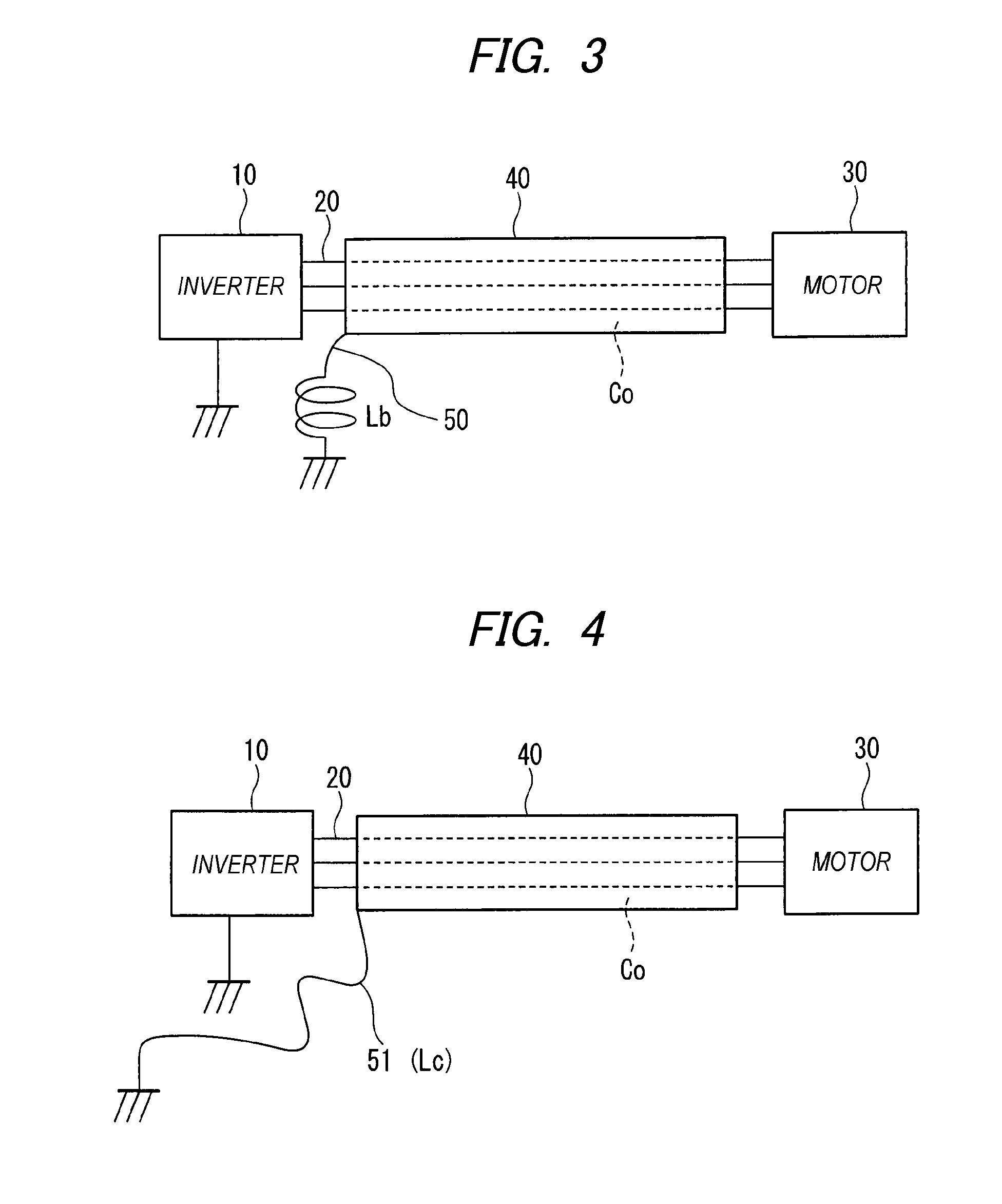
[0075]FIG. 3 is a block diagram of a noise-reducing shielded cable according to Embodiment 3 of the invention.
[0076]In FIG. 3, a three-phase output from an inverter 10 is sent to a motor 30 through a cable 20. Three cables of the cable 20 between the inverter 10 and the motor 30 are covered with a shield layer 40.
[0077]The noise-reducing shielded cable according to Embodiment 3 is characterized in that only an inductor Lb is inserted in a ground wire 50 grounding only one side of the shield layer 40.
[0078]40>
[0079]The shield layer 40 includes three core wires through which a signal is transmitted, and a shield layer that surrounds the three core wires. The shield layer 40 is characterized in that capacitance C0 is provided between the core wires and the shield layer.
[0080]As is understood from FIG. 2, a rigorous shield structure as shown in FIG. 8 does not have to be used between the inverter 10 and the shield layer 40 or between the motor 30 and the shield layer 40 (of course, suc...
PUM
 Abstract
Description
Claims
Application Information
 - R&D Engineer
- R&D Manager
- IP Professional
- Industry Leading Data Capabilities
- Powerful AI technology
- Patent DNA Extraction
Browse by: Latest US Patents, China's latest patents, Technical Efficacy Thesaurus, Application Domain, Technology Topic.
© 2024 PatSnap. All rights reserved.Legal|Privacy policy|Modern Slavery Act Transparency Statement|Sitemap