Wideband Resonant Reflectors with Zero-Contrast Gratings

a resonant reflector and wideband technology, applied in the field of optical devices, can solve problems such as detrimental sensitivity, and achieve the effects of high yield, high responsiveness to parametric changes, and effective manufacturing

Active Publication Date: 2015-12-24
MAGNUSSON ROBERT
View PDF8 Cites 7 Cited by
  • Summary
  • Abstract
  • Description
  • Claims
  • Application Information

AI Technical Summary

Benefits of technology

[0009]A new class of wideband reflectors is provided. A key property of these devices is parametric stability that enables effective manufacturing with high yield. The reflectors are materially sparse while providing high reflectance across wide spectral bands. These compact elements can be made with only a single partially-etched film on a substrate. They complement commercial thin-film multilayer reflectors in wide application spaces while possessing properties not available with traditional thin-film technology. The reflectors are based on a fundamental resonance effect that is gaining global interest. Typically, optical res

Problems solved by technology

In practical applications, where stable spectr

Method used


Image

  • Wideband Resonant Reflectors with Zero-Contrast Gratings
  • Wideband Resonant Reflectors with Zero-Contrast Gratings
  • Wideband Resonant Reflectors with Zero-Contrast Gratings

Examples


example 1

Zero-Contrast Grating Reflector

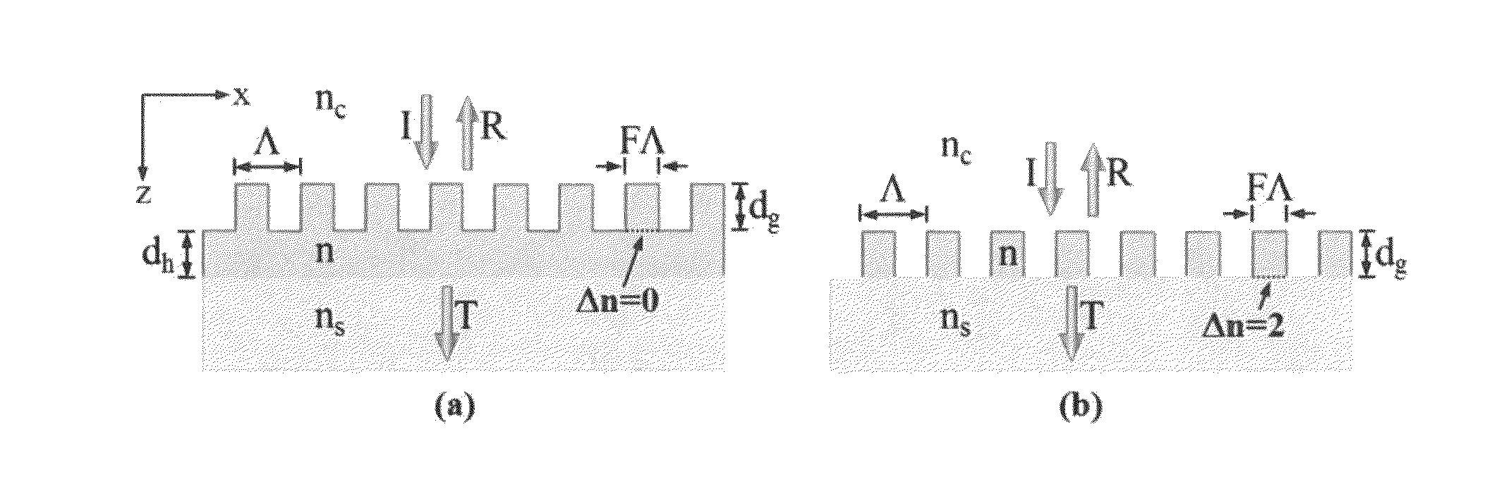
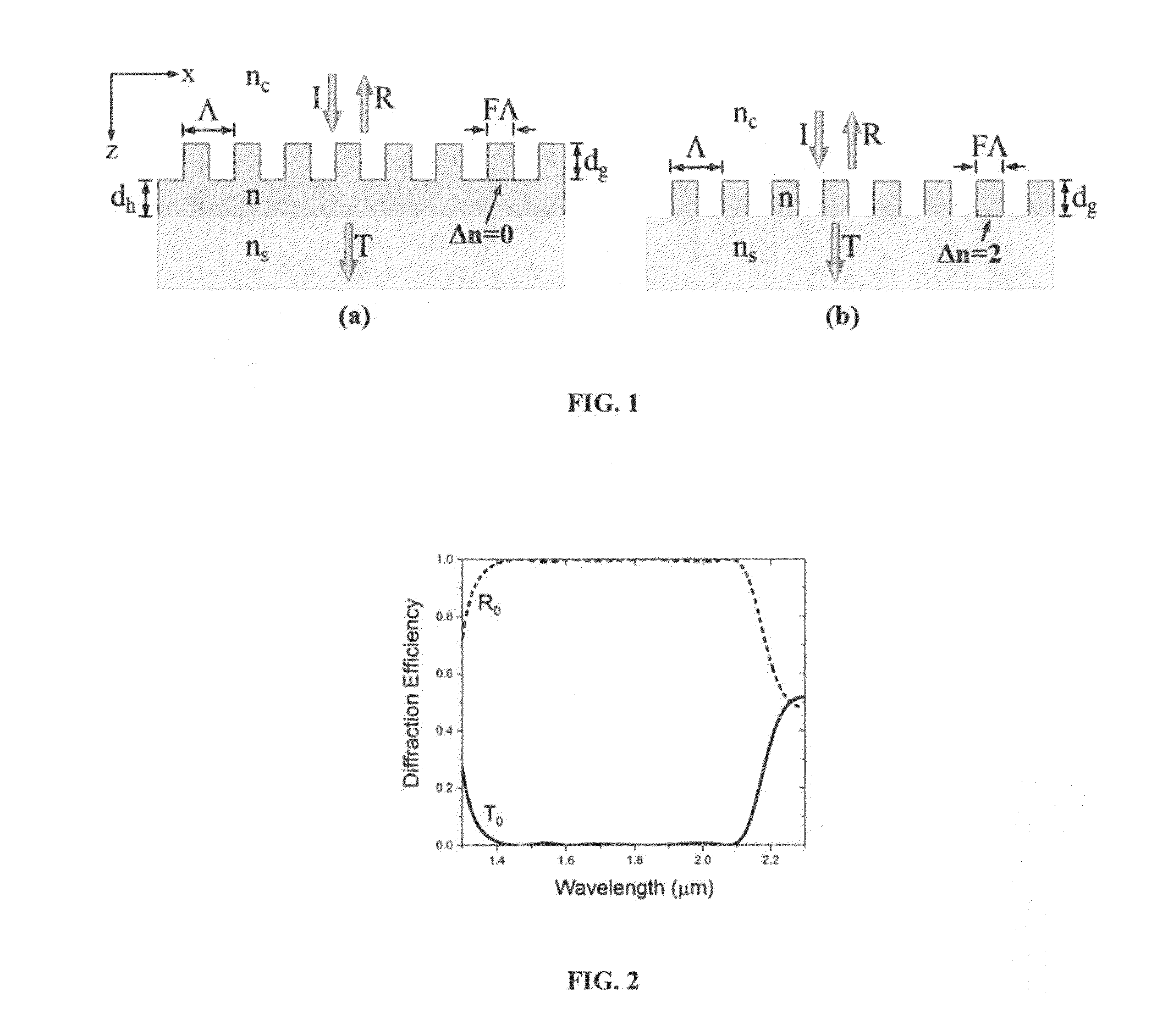
[0037]FIG. 1(a) illustrates a generic zero-contrast grating embodiment pertinent to this disclosure, whose distinctive attributes are as described above. As shown therein, the thickness of the grating, layer is denoted by the thickness of the homogeneous sublayer is in the period is A, and the fill factor is F. In particular, the fill factor for a particular period is expressed, as a ratio of the proportion of grating structure relative to the overall period, and may be stated as F, with the measure of filled space in a period represented by FA, as seen in FIG. 1(a). There is a cover material with index of refraction of nc, device material with refractive index n, and a substrate with refractive index ns on which the device of refractive index n is placed. In some embodiments, the period (A) of a reflector device described herein can be sufficiently small such that only the zero-order transmitted (T0) and reflected (R0) waves propagate external to the ...

example 2

Zero-Contrast Grating Reflector with AR Layer

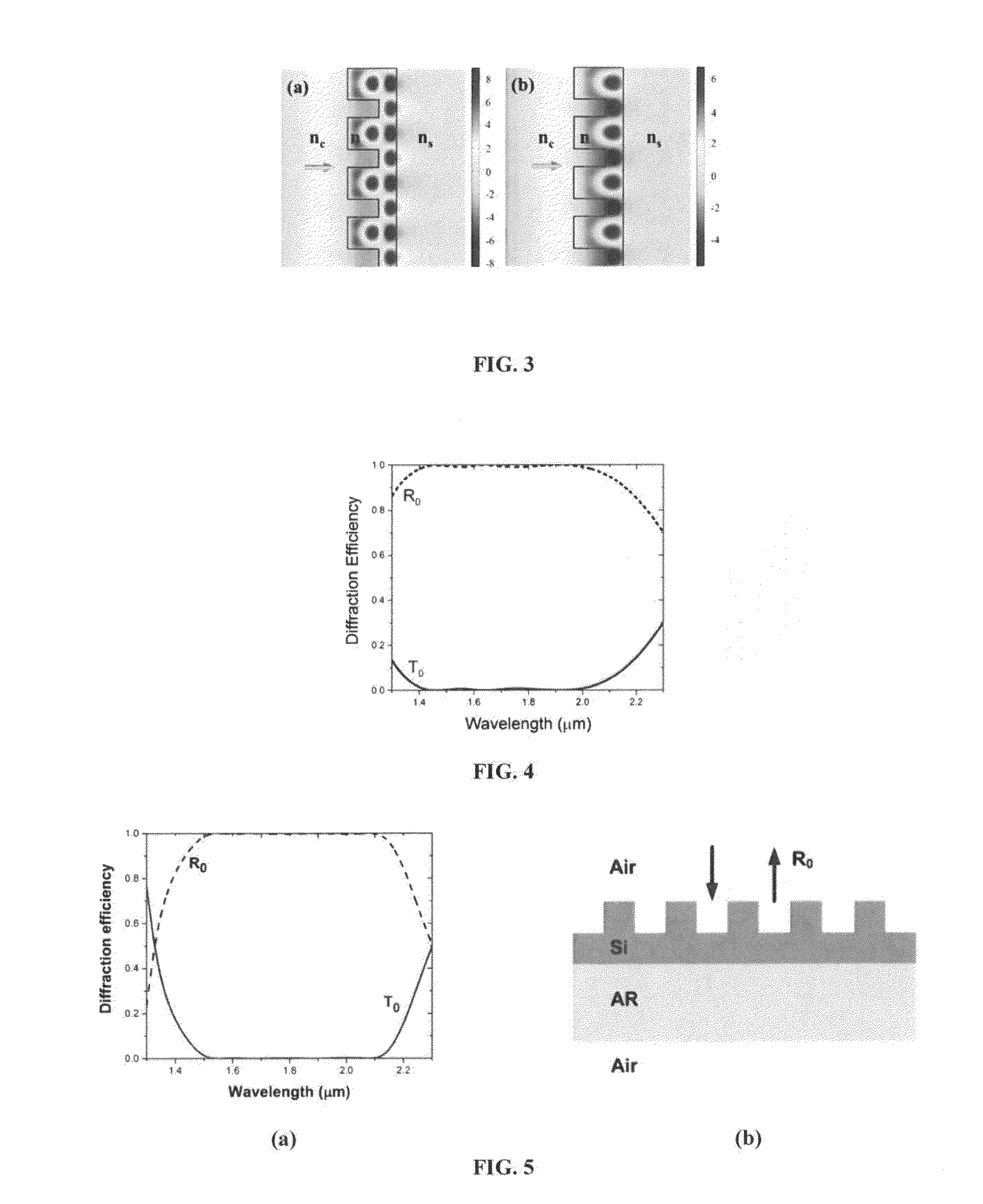
[0038]Assessing the effects of eliminating the z-directed reflection at the ZCG-substrate interface, the substrate in the design in FIG. 2 is replaced with a conventional quarter-wave antireflection (AR) layer centered at 1750 nm, thereby fashioning a membrane in air, FIG. 5(a) shows the resulting zero-order spectra. It is seen that R0>0.99 across a hand exceeding 600 nm in width. FIG. 5(b) shows a schematic of the ZCG membrane with the AR layer attached. The parameter set is dg=490 nm, dh=255 nm, AR layer thickness dAR=235 nm, AR layer refractive index nAR=1.865, A=827 nm, F=0.64, n=3.48, ns=1.48, and nc=1.0. Similar results are-found if a properly designed quarter-wave AR layer is Inserted between the ZCG and the glass substrate in FIG. 2. The conventional single AR layer in FIG. 5(b) can be replaced with improved AR-layer design involving more than one layer.

example 3

Zero-Contrast Grating Reflector with Ultrahigh Reflectance

[0039]For some applications including lasers, it is of interest to increase the reflectance beyond 0.99 to perhaps 0.9999. This can be accomplished within the PSO design strategy by relaxing the spectral bandwidth demand. For example, requiring only 100-nm flat bands for the basic architectures in FIG. 1 yields the results shown in FIG. 6, The ZCG attains R0>0.9999 across 161 nm whereas the HCG only covers 77 nm. The device parameters are as follows: For the ZCG dg=451 nm, dh=623 nm, A=656 nm, and F=0.557; for the HCG dg=490 nm, A=780 nm,and F=0.721. Refractive indices are n=3.48, ns=1.48, and nc=1.0 in both cases, FIG. 7 shows the angular response of these reflectors whose spectra are shown in FIG. 6 at a fixed wavelength of 1550 nm. Both devices provide R0>0.98 out to θ˜10°. Hero 0 is the angle of incidence measured relative to the surface normal of the device, which is the 2-axis in FIG. 1, The ZCG exhibits R0>0.90 for a r...


PUM


Abstract

Disclosed is a new class of wideband reflectors that are relatively insensitive to deviations from the design parameters. The reflectors are materially sparse while providing high reflectance across wide spectral bands. In some embodiments, a device comprises a substrate and a grating layer disposed on the substrate, wherein the grating layer comprises a periodic grating structure and a sublayer beneath the grating structure and adjacent to the substrate, the grating layer and the sublayer having the same index of refraction. These compact, low-loss elements complement conventional thin-film reflectors while possessing properties not available in thin-film multilayer stacks. The reflectors are based on a fundamental resonance effect, the guided-mode resonance effect, that occurs in periodic structures. Disclosed herein are both one-dimensional and two-dimensional reflectors m zero-contrast embodiments. The disclosed reflectors can be used in various electromagnetic spectral regions for various useful applications.

Description

CROSS REFERENCE TO RELATED APPLICATION[0001]This application claims priority pursuant to 35 U.S.C, §119(e) to U.S. Provisional Patent Application Ser. No. 62 / 015,636, filed on Jun. 23, 2014, which is hereby incorporated by reference in its entirety.FIELD[0002]This invention relates to optical devices and, in particular, to reflectors fashioned with zero-contrast gratings exhibiting resonant reflection with wide bandwidth while possessing stability relative to deviation from design parameters as expected under practical fabrication conditions.BACKGROUND OF THE INVENTION[0003]Light's interaction with periodic surfaces and films is of great scientific and technological interest. Numerous device concepts in nanoplasmonics and nanophotonsonics are grounded in intricate resonance effects arising on properly designed structures. In particular, if incident tight couples strongly to a periodic medium, attendant resonance effects may impose diverse spectral signatures on the output light. For...

Claims


Application Information

Patent Timeline
IPC IPC(8): G02B5/18
CPCG02B5/1861G02B1/002G02B5/08
Inventor MAGNUSSON, ROBERT
Owner MAGNUSSON ROBERT
Why Eureka
Try Eureka