Fatigue Resistant Foundation

a foundation and fatigue resistance technology, applied in the direction of foundation engineering, sustainable buildings, manufacturing tools, etc., can solve the problems of compromising the structural integrity of the foundation, affecting the construction efficiency of the foundation, so as to reduce the amount of construction materials and achieve cost-effective effects

Active Publication Date: 2015-12-31
PHULY AHMED
View PDF0 Cites 47 Cited by
  • Summary
  • Abstract
  • Description
  • Claims
  • Application Information

AI Technical Summary

Benefits of technology

[0015]It is desired to have a cost-effective foundation which reduces the amount of construction material used in the construction of wind turbines. This can be accomplished by the use of concrete rib stiffeners, with a cast in place slab on grade element and a central pedestal to build an integral foundation that will behave structurally as a monolithic foundation structure. Other concrete components can be included such as secondary and perimeter beams, diaphragms, or intermediate stiffeners and rib stiffened or flat slab sections. The foundation system may use prefabricated components including rebar meshes and cages, a pedestal cage assembly, precut post-tensioning strands, preassembled strand bundles, precut post-tensioning duct sections and prefabricated concrete forms.

Problems solved by technology

When concrete is cast in massive sections for wind tower foundations, temperatures can reach high levels and the risk of thermal cracking becomes very high unless cooling techniques or special admixtures are applied.
Thermal cracking often compromises the structural integrity of the foundations.

Method used


Image

  • Fatigue Resistant Foundation
  • Fatigue Resistant Foundation
  • Fatigue Resistant Foundation

Examples


Embodiment Construction

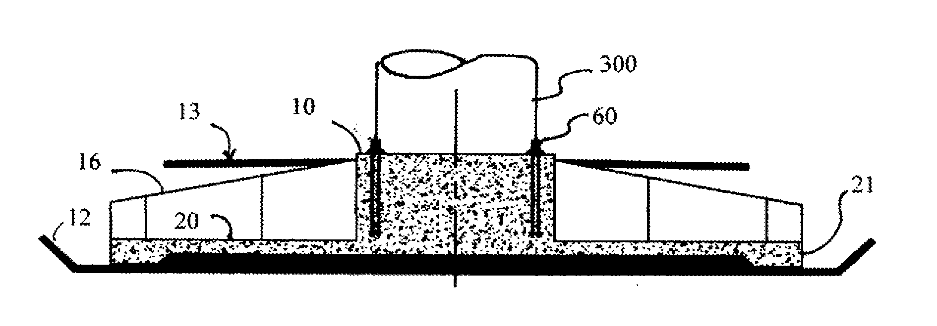
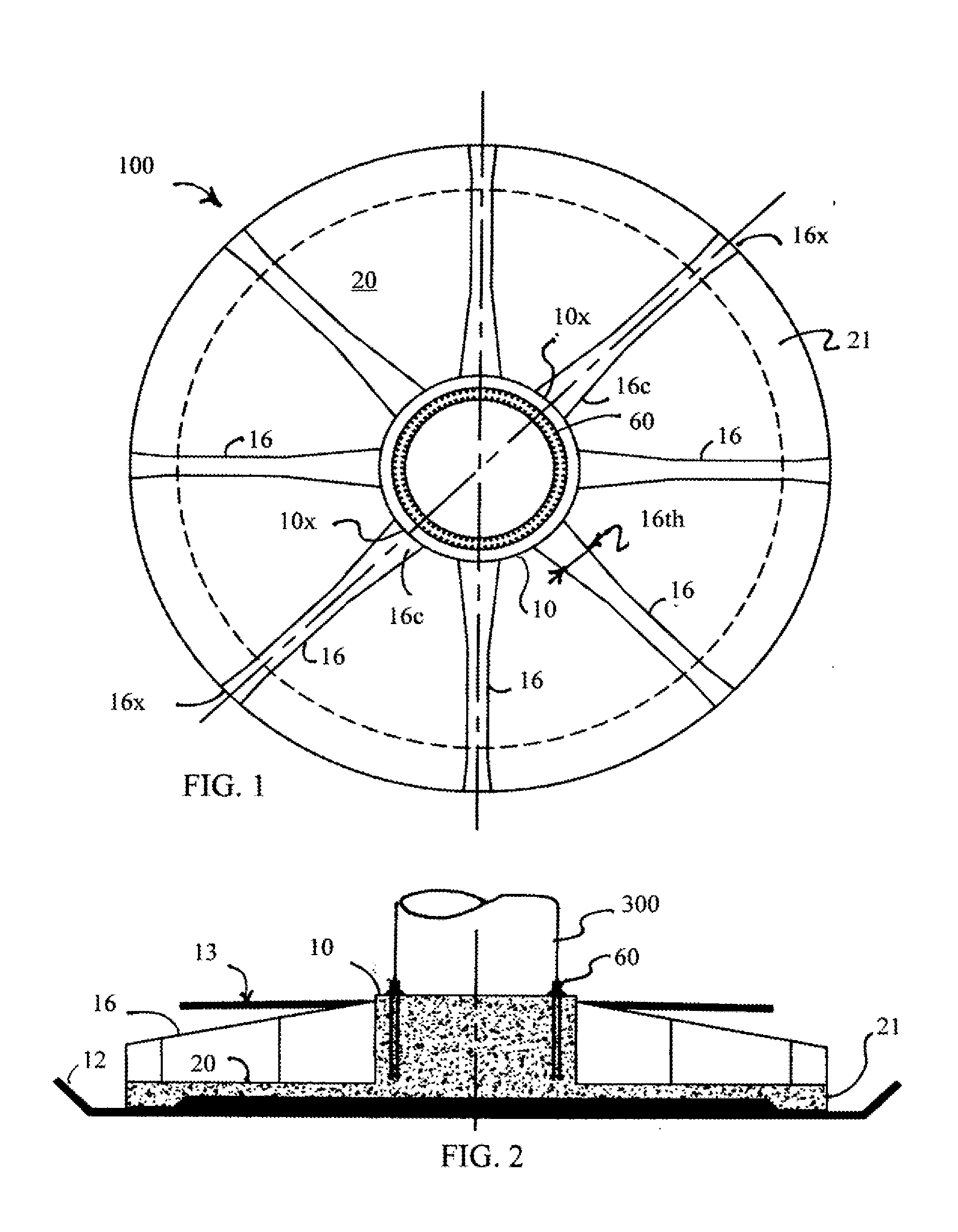
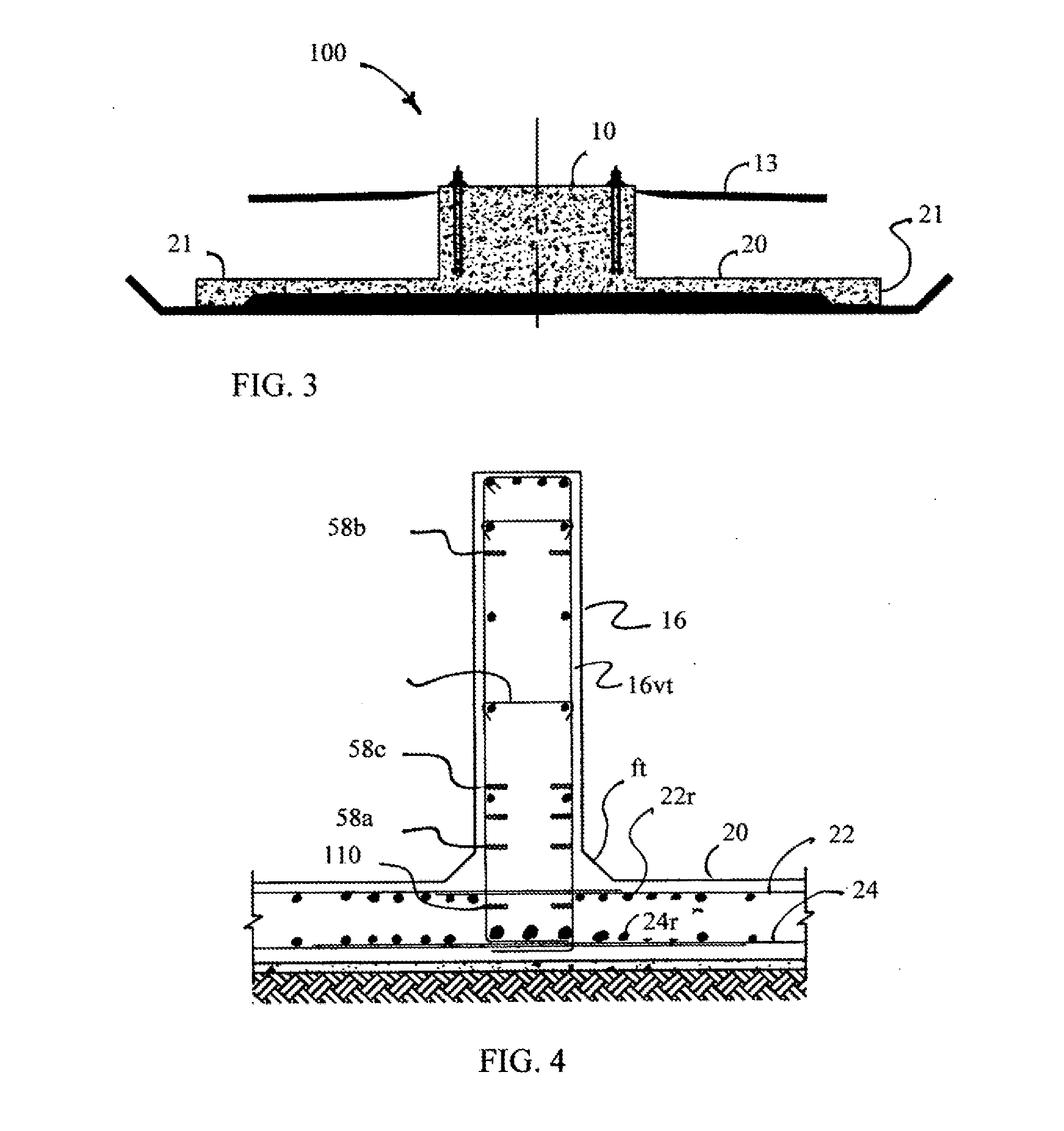
[0114]The present invention pertains to a wind turbine foundation. The foundation comprises a plurality of components, namely a central vertical pedestal, a substantially horizontal bottom support slab, and a plurality of radial reinforcing ribs extending radially outwardly from the pedestal. The ribs may be prefabricated and transported to job site, but the pedestal and support slab are poured in situ at the site out of concrete. Alternatively the ribs may be cast in situ.

[0115]The present invention pertains to a fatigue resistant foundation 100 for wind towers which comprises a plurality of components, namely a central vertical pedestal 10, a substantially horizontal continuous bottom support slab 20 with a stiffened perimeter 21, a plurality of radial reinforcing ribs 16 extending radially outwardly from the pedestal 10 and a three-dimensional network of vertical 56, horizontal 110, 111, 112, diagonal 58b, 58c, radial 58 and circumferential 59 post-tensioning elements embedded in...


PUM

PropertyMeasurementUnit
rated poweraaaaaaaaaa
diameteraaaaaaaaaa
diameteraaaaaaaaaa

Abstract

A fatigue resistant gravity based spread footing under heavy multi-axial cyclical loading of a wind tower. The foundation having a central vertical pedestal, a substantially horizontal continuous bottom support slab, a plurality of radial reinforcing ribs extending radially outward from the pedestal. The pedestal, ribs and slab forming a continuous monolithic structure. The foundation having a three-dimensional network of post-tensioning elements that keep the structural elements under heavy multi-axial post compression with a specific eccentricity intended to reduce stress amplitudes and deflections and allows the foundation to have a desirable combination of high stiffness and superior fatigue resistance. The foundation design reduces the weight and volume of materials used, reduces cost, and improves heat dissipation conditions during construction by having a small ratio of concrete mass to surface area thus eliminating the risk of thermal cracking due to heat of hydration.

Description

CROSS REFERENCE TO RELATED APPLICATIONS[0001]This application is a continuation of Ser. No. 14 / 176,160 filed Feb. 10, 2014 which is continuation of application Ser. No. 13 / 319,083 filed Jul. 5, 2010 now U.S. Pat. No. 8,661,752 issued Mar. 4, 2014, which claims the benefit of provisional applications 61 / 215,430 filed May 5, 2009, 61 / 269,800 filed Jun. 29, 2009, 61 / 284,901 filed Dec. 28, 2009, 61 / 339,550 filed Mar. 5, 2010 and claims priority from PCT / US / 2010 / 041006 and is a continuation-in-part of patent application Ser. No. 12 / 774,727 filed May 6, 2010, which is a continuation-in-part of patent application Ser. No. 11 / 859,588 filed Sep. 21, 2007 which claims the benefit of provisional applications 60 / 826,452 filed Sep. 21, 2006 and 60 / 954,502 filed Aug. 7, 2007.BACKGROUND OF THE INVENTION[0002]1. Field of the Invention[0003]This invention relates to building fatigue resistant foundations for supporting columns, towers and structures under heavy cyclical loads such as for onshore and...

Claims


Application Information

Patent Timeline
Patent Type & Authority Applications(United States)
IPC IPC(8): E02D27/42E04H12/22E02D27/08E04C5/08
CPCF03D13/22E02D2300/002E04H12/16E02D27/425E04C5/08E02D27/08E02D2300/00E04C5/0645E04C5/10Y02B10/30Y02E10/728B28B1/14E02D27/02E02D27/26E04G21/02E04G21/12E04H12/341E02D27/42Y02E10/72
Inventor PHULY, AHMED
Owner PHULY AHMED
Why Eureka
Try Eureka