Energy efficient apparatus employing energy efficient process schemes providing enhanced integration of gasification-based multi-generation and hydrocarbon refining facilities and related methods

a gasification-based multi-generation and energy-efficient technology, applied in the direction of gasifier mechanical details, production gas emission reduction, sustainable manufacturing/processing, etc., can solve the problems of increasing concern over carbon emissions and their effect on the environment, low conversion efficiency, and low thermal efficiency, so as to reduce heating energy-utility-based ghg emissions, reduce pollution, and be significantly more energy-efficient

Active Publication Date: 2015-12-31
SAUDI ARABIAN OIL CO
View PDF4 Cites 84 Cited by
  • Summary
  • Abstract
  • Description
  • Claims
  • Application Information

AI Technical Summary

Benefits of technology

[0078]Various embodiments of the present invention also provide modified configurations of carbon-based-feedstocks-gasification for multi-generation facilities' plants configurations designed to make the whole multi-generation facility energy system more efficient, less polluting, operable at different plants′-specific operating modes, and readily retrofitable upon future expansions.
[0150]According to one or more processing schemes, the gasification plant heating utilities' consumption is advantageously reduced by about 65%, the hydrogen recovery plant heating utilities consumption is reduced by 100%, and the acid gas removal plant heating utility consumption is reduced by about 21%.

Problems solved by technology

However, there is a growing concern over carbon emissions and their effect on the environment.
Tar and methane production, however, is significant at typical operation temperatures, so the product gas must be extensively cleaned before use.
The conversion efficiency can be rather low due to elutriation of carbonaceous material.
Thermal efficiency, however, is somewhat lower as the gas must be cooled before it can be cleaned according to existing technology.
The high temperatures also result in the nonexistence of tar and methane in the product gas.
Some fuels, in particular certain types of biomasses, can form slag that is corrosive to the ceramic inner walls that protect the gasifier outer wall.
Some entrained flow type of gasifiers, however, do not possess a ceramic inner wall, but instead have an inner water or steam cooled wall covered with partially solidified slag.
Additionally of relatively small amounts of limestone will generally lower the fusion temperatures.
Even fuel cells may potentially be used, but these have rather severe requirements regarding the purity of the gas.
A major challenge for waste gasification technologies is to reach an acceptable (positive) gross electric efficiency.
Another challenge when implementing the processes is how to obtain long service intervals, so that it is not necessary to close down the plant every few months for cleaning the reactor.
While small scale gasifiers have existed for well over 100 years, there have been few sources to obtain a ready to use machine.
In some gasification processes, such as slagging gasification, for example, this ash has the form of a glassy solid with low leaching properties, but the net power production in slagging gasification is low or negative, and the costs can be higher.
Power consumption in the gasification and syngas conversion processes can be significant, and can indirectly cause CO2 emissions; and in slagging and plasma gasification, the electricity consumption may even exceed the power production from the produced syngas.
Recognized by the inventor, however, is that although the technology of acid gas removal on a standalone basis is mature in the gas processing industry, its energy integration with the gasification, power generation and condensate handling plants, is not optimally addressed in the public domain.
The wastewater still contains dissolved ash components, which makes the effluent water from the bottom of the stripper 117 unfit for reprocessing as make-up / boiler water.

Method used


Image

  • Energy efficient apparatus employing energy efficient process schemes providing enhanced integration of gasification-based multi-generation and hydrocarbon refining facilities and related methods
  • Energy efficient apparatus employing energy efficient process schemes providing enhanced integration of gasification-based multi-generation and hydrocarbon refining facilities and related methods
  • Energy efficient apparatus employing energy efficient process schemes providing enhanced integration of gasification-based multi-generation and hydrocarbon refining facilities and related methods

Examples


Embodiment Construction

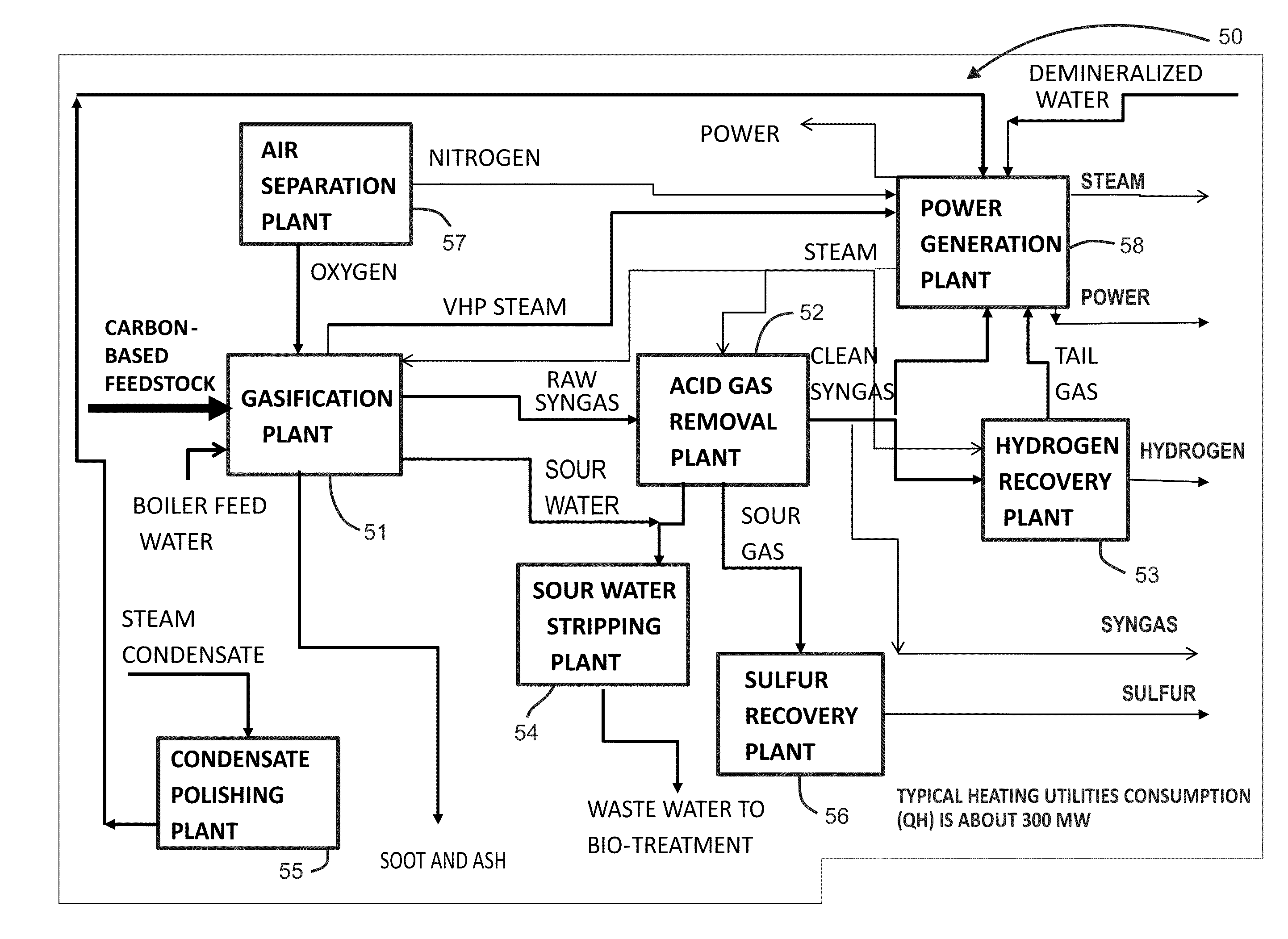
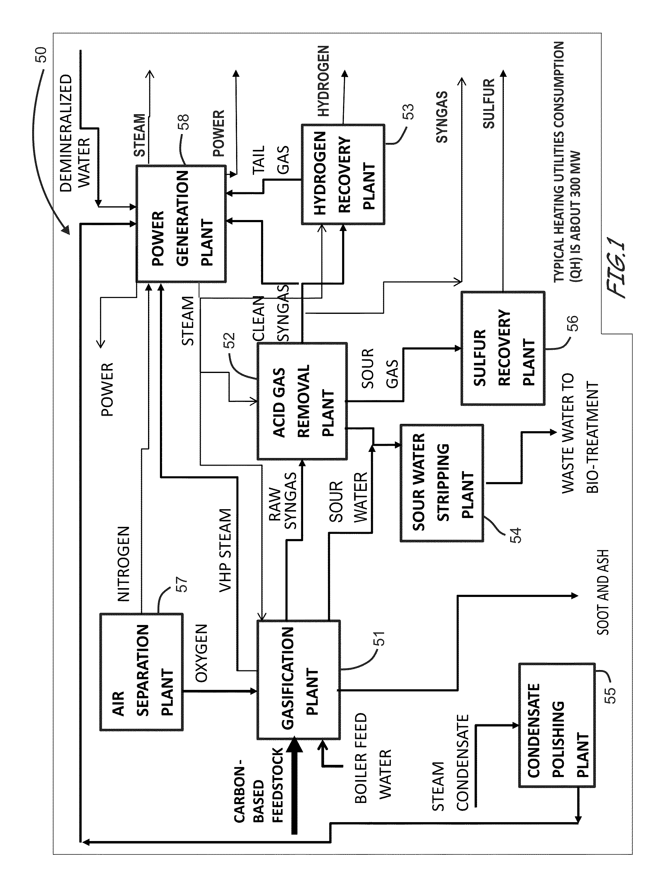
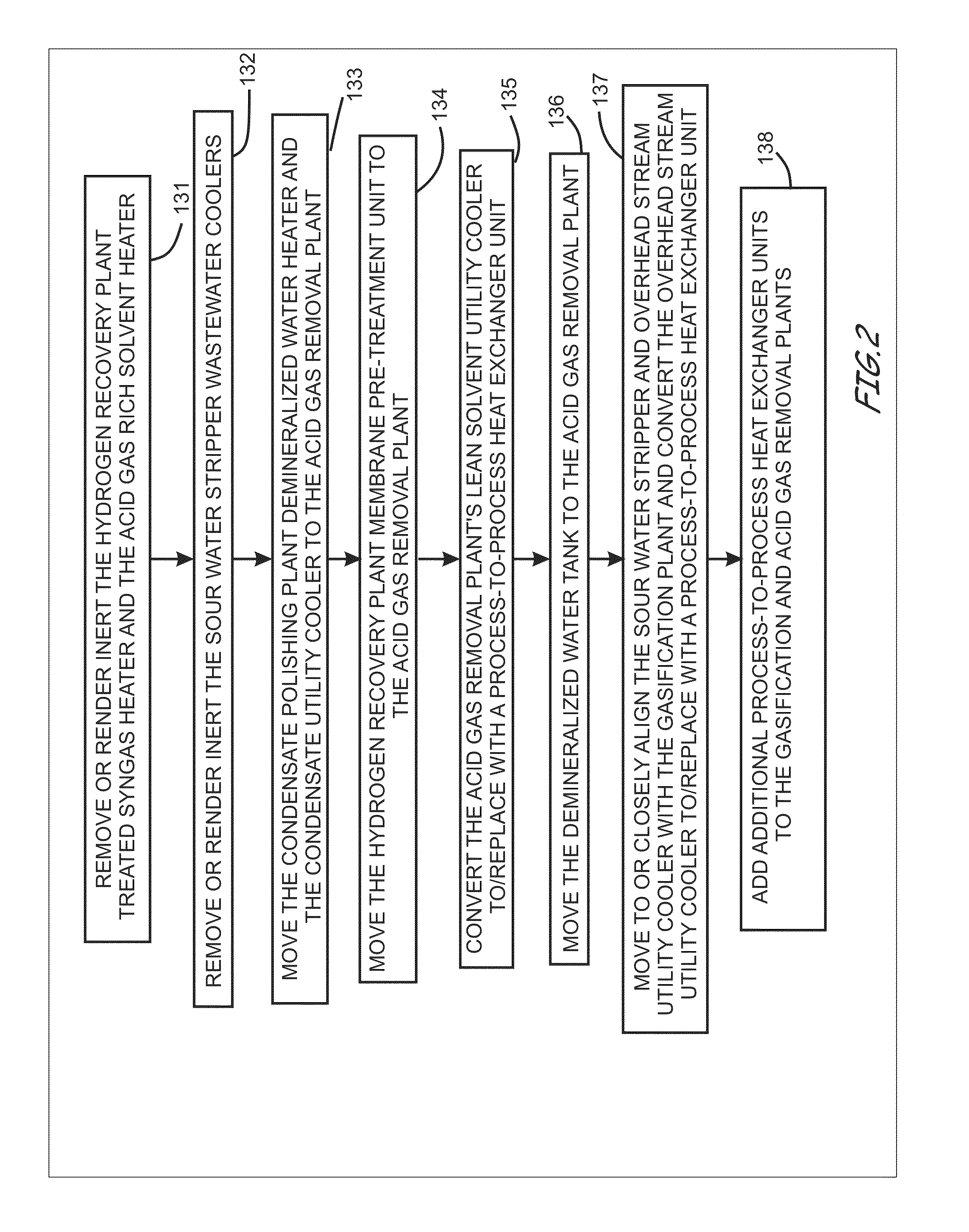
[0181]The present invention will now be described more fully hereinafter with reference to the accompanying drawings, which illustrate embodiments of the invention. This invention may, however, be embodied in many different forms and should not be construed as limited to the illustrated embodiments set forth herein. Rather, these embodiments are provided so that this disclosure will be thorough and complete, and will fully convey the scope of the invention to those skilled in the art. Like numbers refer to like elements throughout. Prime notation, if used, indicates similar elements in alternative embodiments.

[0182]Although specific terms have been employed, the terms themselves were generally used in a descriptive sense only, and unless indicated otherwise, were not used for purposes of limitation. For example, depending upon the context, the terms apparatus, system, and facility in the singular or plural with respect to discussions of multi-generation apparatus, systems, and facil...


PUM

PropertyMeasurementUnit
temperaturesaaaaaaaaaa
temperatureaaaaaaaaaa
heat energyaaaaaaaaaa

Abstract

Energy-efficient gasification-based multi-generation apparatus, facilities, or systems, and methods of modifying existing gasification-based multi-generation apparatus and the various conventional thermal coupling arrangements, are provided. Apparatus for managing waste heat recovery through integration of a gasification-based multi-generation facility or other multi-generation system with a hydrocarbon refining facility or other hydrocarbon refining system and methods of providing the respective integration are also provided. An exemplary apparatus includes an integrated site energy management system configured according to one or more process-based thermal coupling schemes comprising one or more thermal coupling arrangements between a gasification-based multi-generation system or facility and a hydrocarbon refining system or facility. The gasification-based multi-generation system or facility can include an acid gas removal system or plant configured to remove acidic contaminants from a raw syngas feed to thereby provide a treated syngas feed, the acid gas removal system or plant containing a separation section including a solvent regenerator, and a gasification system configured to generate the raw syngas feed from a carbon-based feedstock. The hydrocarbon refining system or facility can include an aromatics system or plant containing a xylene products separation section including one or more of the following: an Extract column and a Raffinate column. The integrated site energy management system can include a hot-water system extending between the separation section of the acid gas removal system or plant and the xylene products separation section of the aromatics system or plant, and a plurality of added heat exchanger units providing various advanced thermal coupling arrangements.

Description

RELATED APPLICATIONS[0001]This application claims priority to and the benefit of U.S. Provisional Patent Application Ser. No. 62 / 018,604, by Noureldin, titled “Energy Efficient Gasification Based Multi Generation Apparatus Employing Advanced Process Schemes and Related Methods” filed on Jun. 28, 2014, which is related to U.S. patent application Ser. No. 13 / 099,144, by Noureldin, titled “Energy-Efficient and Environmentally Advanced Configurations for Naptha Hydrotreating Process” filed on May 2, 2011, which are each incorporated herein by reference in their entireties. This application also relates to: U.S. patent application Ser. No. ______, by Noureldin, titled “Energy Efficient Gasification Based Multi Generation Apparatus Employing Advanced Process Schemes and Related Methods” filed on the same day as this application, Apr. 21, 2015; U.S. patent application Ser. No. ______, by Noureldin, titled “Energy Efficient Gasification Based Multi Generation Apparatus Employing Energy Effi...

Claims


Application Information

Patent Timeline
Patent Type & Authority Applications(United States)
IPC IPC(8): F01K25/10B01J19/24B01J19/00C10J3/20
CPCC10J3/82B01D3/007C10J2200/09C10K1/003C10K1/02C10K1/101B01J19/0006B01J19/24B01J2219/00103B01J2219/24C10J3/20C10J2200/00F01K25/10C10K1/046C10J3/00C10J3/80C10K1/10C10J2300/169C10J2300/1861C10J2300/1869C10J2300/1884C10J2300/1892Y02E20/18Y02P20/129Y02P20/124Y02P30/10C10J3/84C10J3/72C10J2300/0959C10J2300/1671C10J2300/1678C10J2300/1693C10J2300/1687Y02P20/10Y02P30/00
Inventor NOURELDIN, MAHMOUD BAHY
Owner SAUDI ARABIAN OIL CO
Why Eureka
Try Eureka