Heat dissipating fin assembly

a technology of heat dissipation fins and components, which is applied in the direction of machines/engines, liquid fuel engines, lighting and heating apparatus, etc., can solve the problems affecting the reliability of products, and achieve the effects of reducing and increasing the density of heat dissipation structures

Inactive Publication Date: 2015-12-31
DELTA ELECTRONICS INC
View PDF8 Cites 4 Cited by
  • Summary
  • Abstract
  • Description
  • Claims
  • Application Information

AI Technical Summary

Benefits of technology

[0008]In view of the foregoing subject, an objective of the present invention is to provide a heat dissipating fin assembly which can provide a dusting function easily so as to improve the heat dissipating efficiency.
[0025]As mentioned above, the inner end of the heat dissipating fin assembly of the invention has lower density of heat dissipating structure (the first heat dissipating fins), and the outer end of the heat dissipating fin assembly has higher density of heat dissipating structure (including the first and second heat dissipating fins). The lower density heat dissipating structure at the inner end can avoid the accumulation of dusts, and the higher density heat dissipating structure at the outer end can maintain a larger heat dissipating surface area. The heat dissipating fin assembly further includes an inner cover plate and an outer cover plate, and an opening is defined between the inner and outer cover plates. As a result, the dusts can be exhausted through the opening, thereby achieving the effects of dusting and improved heat dissipating efficiency.
[0026]In another embodiment, the inner end of the heat dissipating fin assembly has lower density of heat dissipating structure (the first fin bodies), and the outer end of the heat dissipating fin assembly has higher density of heat dissipating structure (including the first and second fin bodies). In addition, the first inner cover extension portion, the first outer cover extension portion and the second outer cover extension portion form an opening. This configuration can also provide a lower density heat dissipating structure at the inner end to avoid the accumulation of dusts, and a higher density heat dissipating structure at the outer end to maintain a larger heat dissipating surface area. Besides, the dusts entering the heat dissipating fin assembly through the inner end can be ejected via the opening.

Problems solved by technology

However, these features make the internal temperature of the electronic products become higher and higher, which may cause the product unstable and thus affect the reliability of the products.

Method used


Image

  • Heat dissipating fin assembly
  • Heat dissipating fin assembly
  • Heat dissipating fin assembly

Examples


Embodiment Construction

[0051]The present invention will be apparent from the following detailed description, which proceeds with reference to the accompanying drawings, wherein the same references relate to the same elements.

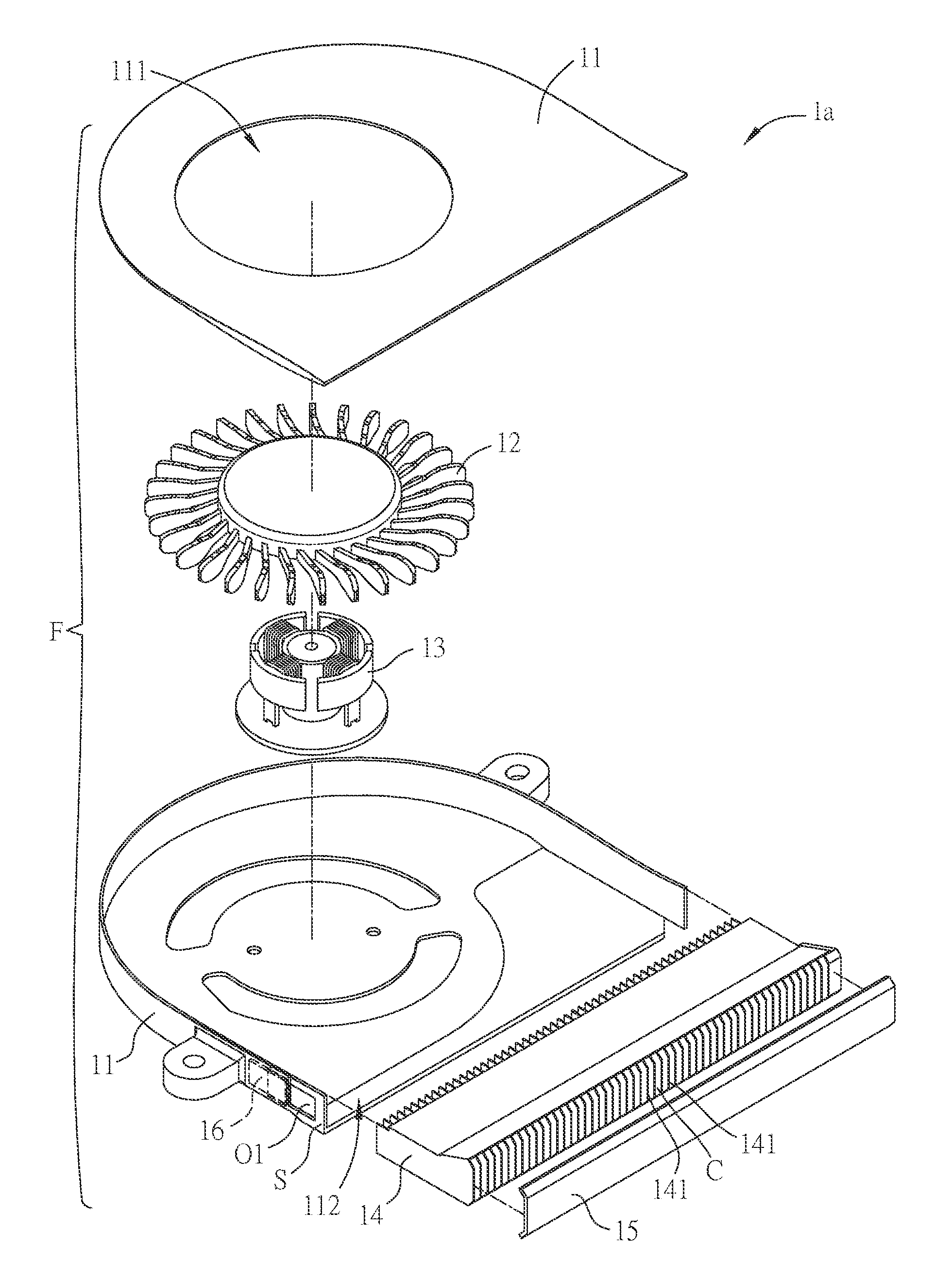
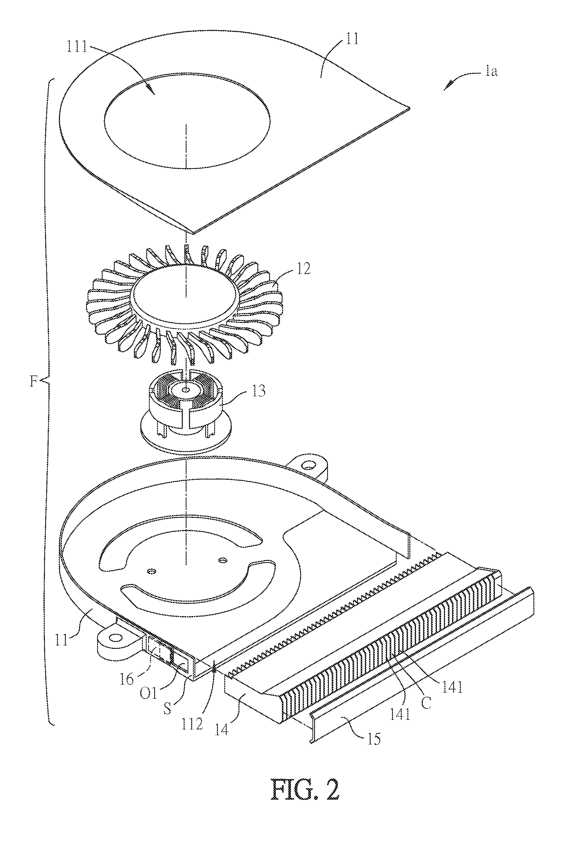
[0052]FIG. 1 is a schematic diagram showing an assembled heat dissipating device la according to an embodiment of the invention, FIG. 2 is an exploded view of the heat dissipating device 1a of FIG. 1, and FIG. 3 is a schematic diagram showing a part of the assembled heat dissipating device 1a of FIG. 1. Referring to FIGS. 1 and 2, the heat dissipating device 1a of this embodiment includes a fan F, a heat dissipating fin assembly 14 and a block 15. The fan F includes a fan frame 11, an impeller 12 and a motor 13. The motor 13 is disposed in the fan frame 11. The impeller is mounted on the motor 13, so that the motor 13 is connected to the impeller 12 and drives it to rotate. The fan frame 11 has an inlet 111 and an outlet 112. The heat dissipating fin assembly 14 is disposed at the pos...


PUM


Abstract

A heat dissipating fin assembly includes a bottom plate, a plurality of first heat dissipating fins, a plurality of second heat dissipating fins, an inner cover plate and an outer cover plate. The first heat dissipating fins extend from an inner end to an outer end. The second heat dissipating fins are located between two of the first heat dissipating fins. The inner cover plate is disposed at the inner end and connected to the first heat dissipating fins. The outer cover plate is disposed at the outer end and connected to the second heat dissipating fins. The outer cover plate and the inner cover plate are separated so as to form an opening. The second heat dissipating fins extend from around the opening to the outer end. The length of the first heat dissipating fins is larger than that of the second heat dissipating fins.

Description

CROSS REFERENCE TO RELATED APPLICATIONS[0001]This Non-provisional application claims priority under 35 U.S.C. §119(a) on Patent Application No(s). 103122426 filed in Taiwan, Republic of China on Jun. 27, 2014, the entire contents of which are hereby incorporated by reference.BACKGROUND OF THE INVENTION[0002]1. Field of Invention[0003]The present invention relates to a heat dissipating fin assembly and, in particular, to a heat dissipating fin assembly with dusting function.[0004]2. Related Art[0005]The electronic products are developed with higher performance, higher frequency, higher speed, and lighter and thinner structure. However, these features make the internal temperature of the electronic products become higher and higher, which may cause the product unstable and thus affect the reliability of the products. Therefore, the existing electronic products are usually equipped with a fan to dissipate the generated heat.[0006]Regarding to a common heat-dissipating fan, the outlet o...

Claims


Application Information

Patent Timeline
Patent Type & Authority Applications(United States)
IPC IPC(8): F28F3/02
CPCF28F3/02F28F2250/08F28F19/00F28F2215/04F04D17/16F04D29/5826
Inventor YANG, SHU-CHENGCHANG, CHIH-HSIANGCHEN, SHIH-CHOU
Owner DELTA ELECTRONICS INC
Why Eureka
Try Eureka