
A method and an apparatus for predicting the condition of a machine or a component of the machine

a technology for predicting the condition of a machine or a component, applied in the direction of machine part testing, registering/indicating the working of the machine, measurement/indication equipment, etc., to achieve the effect of improving the estimation of the most cost-effective point and improving the prediction of a condition monitoring parameter

Active Publication Date: 2015-12-31
E MAINTENANCE SWEDEN AB
View PDF9 Cites 12 Cited by
  • Summary
  • Abstract
  • Description
  • Claims
  • Application Information

AI Technical Summary

Benefits of technology

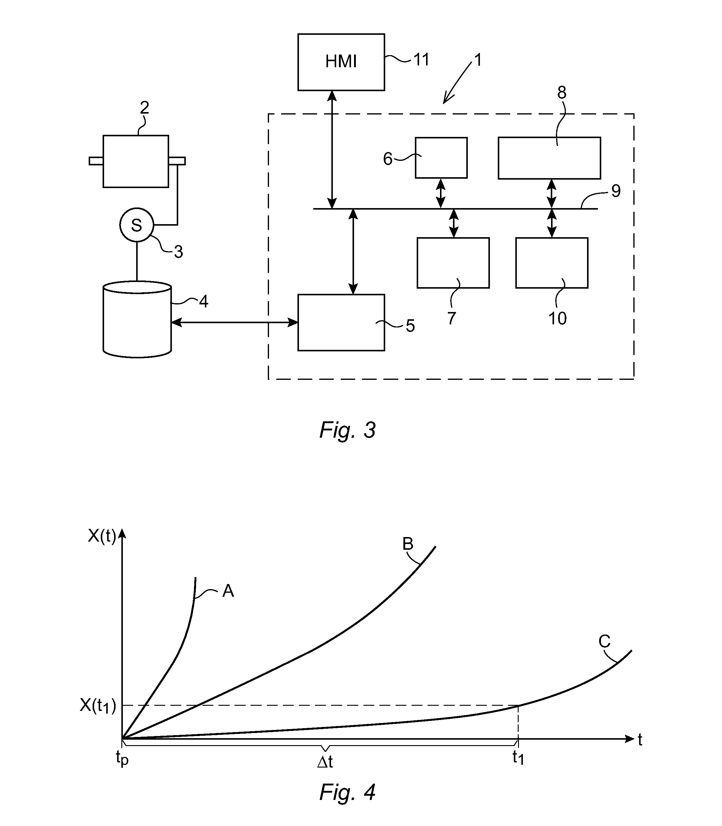
The present invention aims to improve the prediction of a condition monitoring parameter, which helps the estimation of the most cost-effective time for replacing or maintenance of the machine or significant components of the machine. The prediction is made based on the cleaned measurement values stored in the moving window, which includes at least three stored measurement values. This helps to provide early warnings and maintenance instructions to the user. The method also involves comparing the predicted level of the condition monitoring parameter with at least one limit level for the parameter, and proposing a maintenance action when the predicted level exceeds the limit level. This embodiment makes it possible to propose a maintenance action with enough lead time at a cost-effective point in time.

Problems solved by technology

The raw measurement data is often influenced by disturbances that affect the result of the prediction.

Method used


Image

  • A method and an apparatus for predicting the condition of a machine or a component of the machine
  • A method and an apparatus for predicting the condition of a machine or a component of the machine
  • A method and an apparatus for predicting the condition of a machine or a component of the machine

Examples


Embodiment Construction

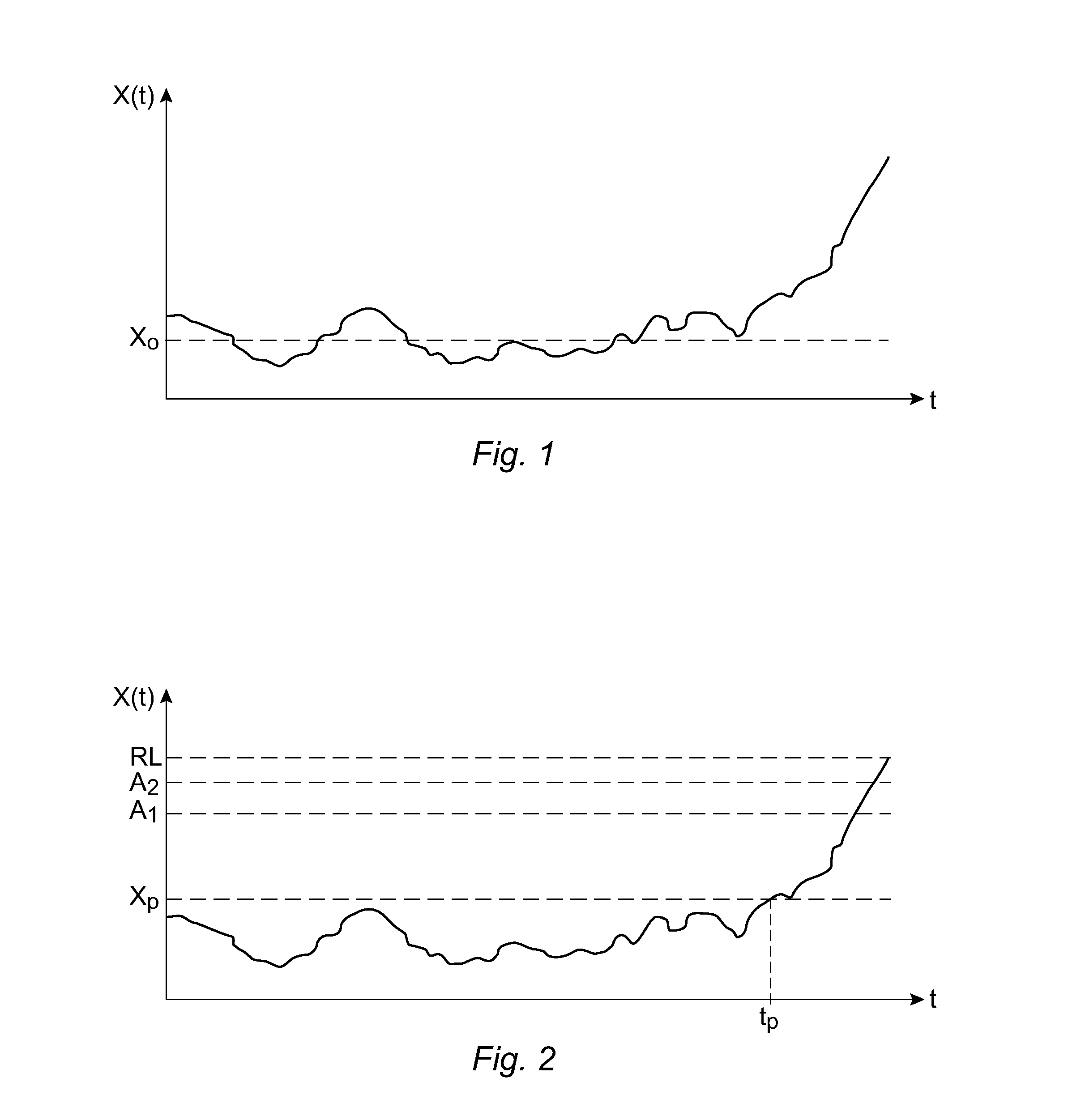
[0030]FIG. 2 shows an example of how measurement of a condition monitoring parameter may vary over time before and after damage has been initiated. A potential failure level XP of a condition monitoring parameter has been defined, at which level damage of the machine or component is considered initiated. Further two limit levels A1, A2 for generating maintenance instructions have been defined. A replacement level RL is also shown in the figure. When the replacement level has been approached or reached, the component or the machine must be replaced. The number of limit levels for generating maintenance instructions may vary. In one embodiment, only one limit level may be defined. It is also possible to have several limit levels, and to generate a special message for every particular limit level and component in a machine, identifying which machine (if there are several machines included), showing component location, component damage severity, number of days left until the time of the...


PUM


Abstract

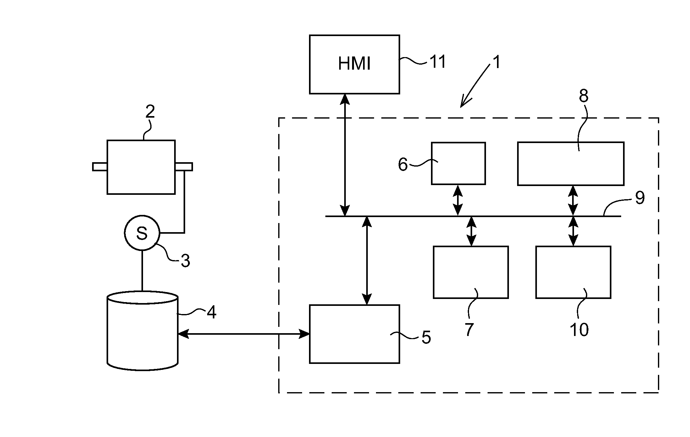
The present invention relates to a method and an apparatus for predicting the condition of a machine or a component of the machine based on measurements of a condition monitoring parameter. The apparatus comprising—a data storage (6) for storing a moving window including measurement values of the condition monitoring parameter,—a monitoring module (7) configured to determine when a measurement value exceeds a potential failure level at which damage of the machine or component is considered initiated, and to determine the point in time (tP) when the monitoring parameter exceeded the potential failure level,—a data cleaning module (8) configured to discard a new measurement value if it is smaller than the latest stored measurement value in the moving window, to determine an expected value for the measurement based on a defined pattern for the condition monitoring parameter, which pattern reflects an expected behavior of the monitoring parameter after damage has been initiated, and the time elapsed since the point in time the monitoring parameter exceeded the potential failure level, and to discard the new measurement value if it deviates too much from the expected value, and to store not discarded measurement values in the moving window, and—a prediction module (10) configured to predict the level of the condition monitoring parameter at a future point in time based on the measurement values stored in the moving window.

Description

FIELD OF THE INVENTION[0001]The present invention relates to a method and an apparatus for predicting the condition of a machine, such as a rotating machine, or a component of the machine, for example, a bearing, gear, gearbox, pump, electrical motor, turbine, or compressor.PRIOR ART[0002]In production processes it is necessary to apply condition monitoring (CM) to reduce downtime and prolong production time, as well as to improve the productivity and product quality in order to reduce production cost and increase profit continuously. Thus, the condition of a machine and / or significant components of the machine should be monitored during the lifetime of the machine.[0003]The condition of a mechanical component degrades gradually through structural, surface and subsurface deterioration. The time and extent of deterioration depends on many factors, such as construction, material, operating and environmental conditions. The life of a machine or a significant component includes three di...

Claims


Application Information

Patent Timeline
Patent Type & Authority Applications(United States)
IPC IPC(8): G01M99/00G01M13/00
CPCG05B23/024G01M13/00G07C3/00G05B23/0283G01M99/005B23Q17/12G05B19/4065
Inventor AL-NAJJAR, BASIM
Owner E MAINTENANCE SWEDEN AB
Learn More