Analog Floating-Gate Atmometer

an atmometer and floating gate technology, applied in the field of electronic sensors, can solve the problems of data transmission from one atmometer, inconvenient automation of the other, and the frequency at which measurements can be obtained from those conventional atmometers is necessarily limited, so as to achieve the effect of rapid and frequent measurement of the evaporation ra

Active Publication Date: 2015-12-31
TEXAS INSTR INC
View PDF2 Cites 6 Cited by
  • Summary
  • Abstract
  • Description
  • Claims
  • Application Information

AI Technical Summary

Benefits of technology

[0009]Disclosed embodiments provide a device, system, and method for rapidly and frequently measuring evaporation rate.
[0012]Disclosed embodiments provide such a device that can be fabricated using conventional integrated circuit manufacturing technology, and thus at low cost.
[0013]Disclosed embodiments provide such a device, system, and method that can be calibrated and thus provide repeatable and reliable measurements.

Problems solved by technology

The frequency at which measurements can be obtained from those conventional atmometers is necessarily limited, and as such these measurements are each essentially averaged over relatively long time periods (e.g., at least a few hours).
In addition, because the evaporation rate measurement is typically obtained by visual inspection of the reservoir level, these conventional atmometers are not conducive to automation.
A recent trend, however, is the increasing deployment of networked communications among computer systems and other electronic devices themselves, absent human initiation or control of the communications.
The amount of data transmitted from one “machine” to another in a given transmission is often quite small (e.g., streaming video is not often involved), and is often not particularly time-sensitive.

Method used


Image

  • Analog Floating-Gate Atmometer
  • Analog Floating-Gate Atmometer
  • Analog Floating-Gate Atmometer

Examples


Embodiment Construction

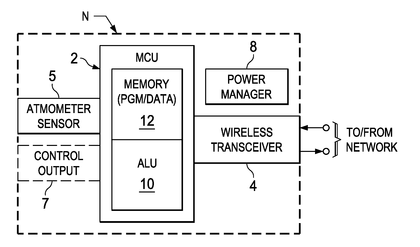
[0024]The one or more embodiments described in this specification are implemented into an atmometer system or device implemented in a networked arrangement, such as according to the “Internet of Things” (IoT), as it is contemplated that such implementation is particularly advantageous in that context. However, it is also contemplated that concepts of this invention may be beneficially applied to in other applications, such as stand-alone devices or as integrated into manufacturing, environmental, or other equipment for which measurement of evaporation rate is useful. Accordingly, it is to be understood that the following description is provided by way of example only, and is not intended to limit the true scope of this invention as claimed.

[0025]As mentioned above in the Background of the Invention, it is contemplated that distributed networked systems consisting of a number of sensors and controllers that each contain significant computational capacity and are capable of M2M commun...


PUM

PropertyMeasurementUnit
timeaaaaaaaaaa
resistanceaaaaaaaaaa
floating-gate capacitanceaaaaaaaaaa

Abstract

An atmometer system based on an analog floating-gate structure and circuit. The floating-gate circuit includes a floating-gate electrode that serves as a gate electrode for a transistor and a plate of a storage capacitor. A conductor element exposed at the surface of the integrated circuit is electrically connected to the floating-gate electrode; reference conductor elements biased to ground are also at the surface of the integrated circuit. In operation, the transistor is biased and moisture is dispensed at the surface. The drain current of the transistor changes as the floating-gate electrode discharges via the surface conductors and a conduction path presented by the moisture. The elapsed time until the drain current stabilizes indicates the evaporation rate.

Description

CROSS-REFERENCE TO RELATED APPLICATIONS[0001]This application claims priority, under 35 U.S.C. §119(e), of Provisional Application No. 62 / 018,248, filed Jun. 27, 2014, incorporated herein by this reference.STATEMENT REGARDING FEDERALLY SPONSORED RESEARCH OR DEVELOPMENT[0002]Not applicable.BACKGROUND OF THE INVENTION[0003]This invention is in the field of electronic sensors. Embodiments disclosed in this specification include electronic sensors for sensing evaporation rate and relative humidity.[0004]Atmometers are instruments for measuring the rate at which water evaporates from a wet surface into the atmosphere. Evaporation rate and related parameters are of particular importance in agriculture, among other industries. For example, knowledge of the rate at which plants transpire can assist the scheduling of irrigation activities, both in timing and in the amount of water applied to the crops. Efficient use of available water is, of course, especially important in arid regions, or t...

Claims


Application Information

Patent Timeline
Patent Type & Authority Applications(United States)
IPC IPC(8): G01N27/12G01N7/16
CPCG01N2015/0026A01G25/00G01N15/0606H01L29/788G01N2035/00881G01N27/223A01G25/167G01N15/0656
Inventor MITCHELL, ALLAN T.ESKEW, MARK
Owner TEXAS INSTR INC
Why Eureka
Try Eureka