Configurable microwave deflection system

a deflection system and microwave technology, applied in the direction of electrical equipment, antennas, etc., can solve the problems of additional mechanical systems, maintenance and preventive maintenance costs, and electrical consumption to maintain, and achieve high deflection angles, strong attenuation, and high effectiveness

Active Publication Date: 2015-12-31
THALES SA
View PDF4 Cites 13 Cited by
  • Summary
  • Abstract
  • Description
  • Claims
  • Application Information

AI Technical Summary

Benefits of technology

[0030]The object of the invention is to remedy the abovementioned drawbacks, by proposing a compact and lightweight deflection system that makes it possible to obtain high deflection angles, a high effectiveness on the main order of diffraction corresponding to the main direction of the deflection, and a strong attenuation of the other orders of diffraction.

Problems solved by technology

The drawbacks are the addition of an extra mechanical system, in weight / volume (relative to the location of a mast), a sphere of significant bulk, as seen from the outside, which changes volume according to its orientation, the reliability (above all if a “remote” antenna is wanted), and the servicing and preventive maintenance costs.
However, this solution presents the following drawbacksa complex system: a phase shifter is needed for each individual antenna and a control is needed for each phase shifter, hence an associated power supply.
To facilitate this cable management, the wires are often incorporated in printed circuits to facilitate the “management” of the cables;the phase shifters in certain cases have difficulty supporting the power, hence a power limitation,the presence of the phase shifters requires the effects of the power and of the temperature to be taken into account, and therefore requires the addition of a cooling system to extract the energy,this technology is costly,this technology involves electrical consumption to maintain the control, even when the antenna is not operating.
A drawback of this system for its application to microwave frequencies is the bulk of the deflector resulting from the thickness of the prisms.
Furthermore, as with solid prisms, the greater the diameter (or aperture) of the deflection system, the greater the diameter of the components, which leads to an increase in their thickness (given the same material) to obtain the desired deviation, resulting in a component that is all the more bulky.
However, when a strong deviation is required, for example at least equal to + / −20°, this solution is no longer suitable because it induces losses that increase with the angle of diffraction, because of the shadowing effect.
Furthermore, when the angle of the first order diffracted beam increases, which corresponds to a period P of the grating which decreases, the energy diffracted in the other orders of the grating or secondary orders increases, also inducing a loss on the diffraction effectiveness of the grating, and therefore on the intensity of the deflected microwave frequency beam.

Method used


Image

  • Configurable microwave deflection system
  • Configurable microwave deflection system
  • Configurable microwave deflection system

Examples


Embodiment Construction

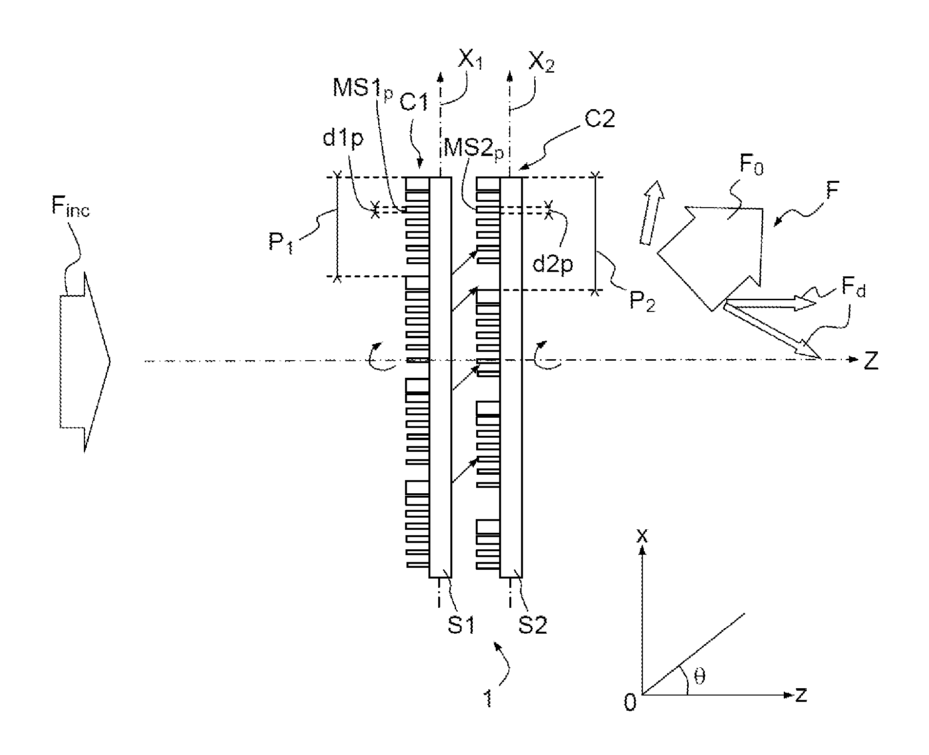
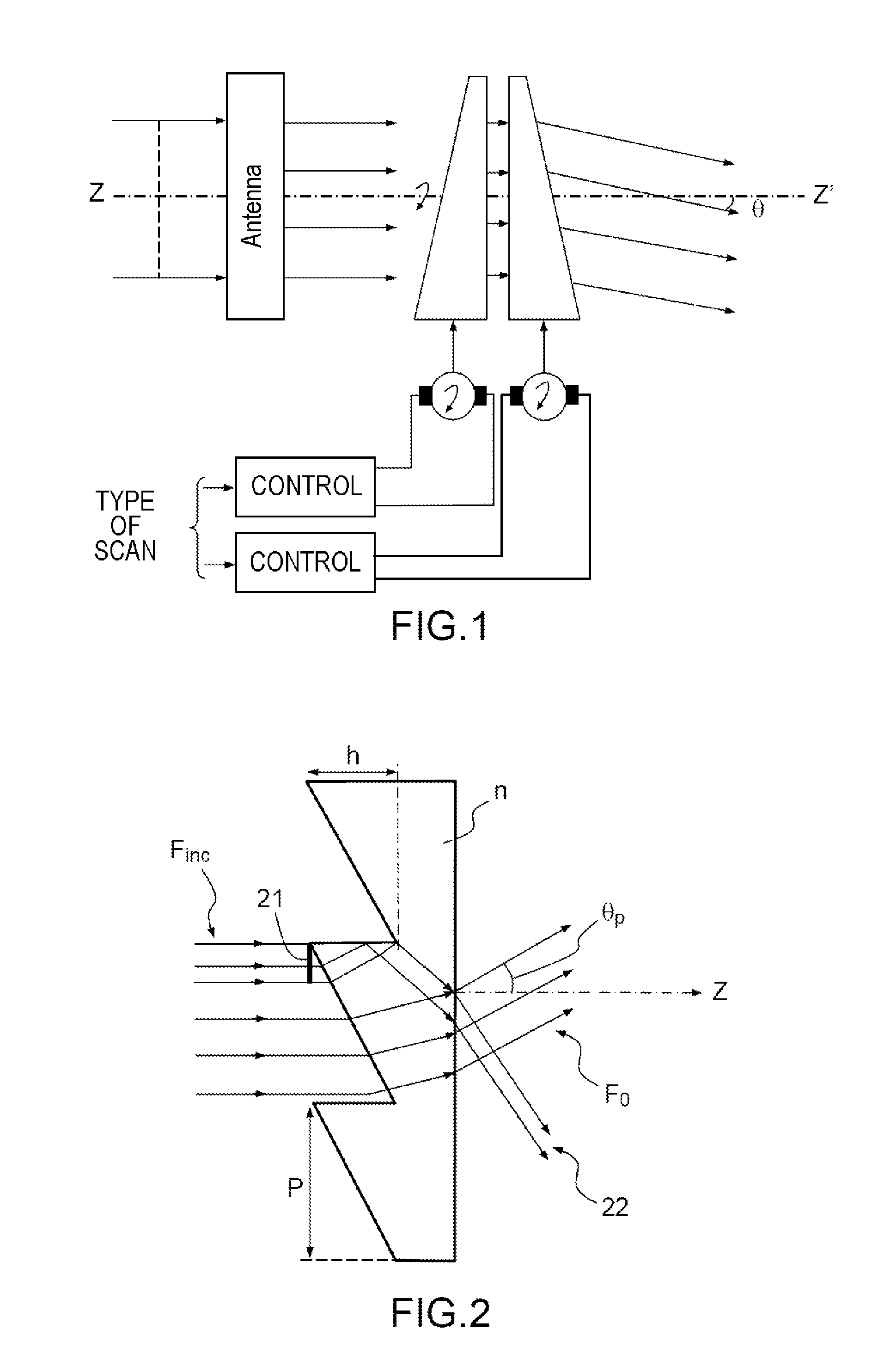
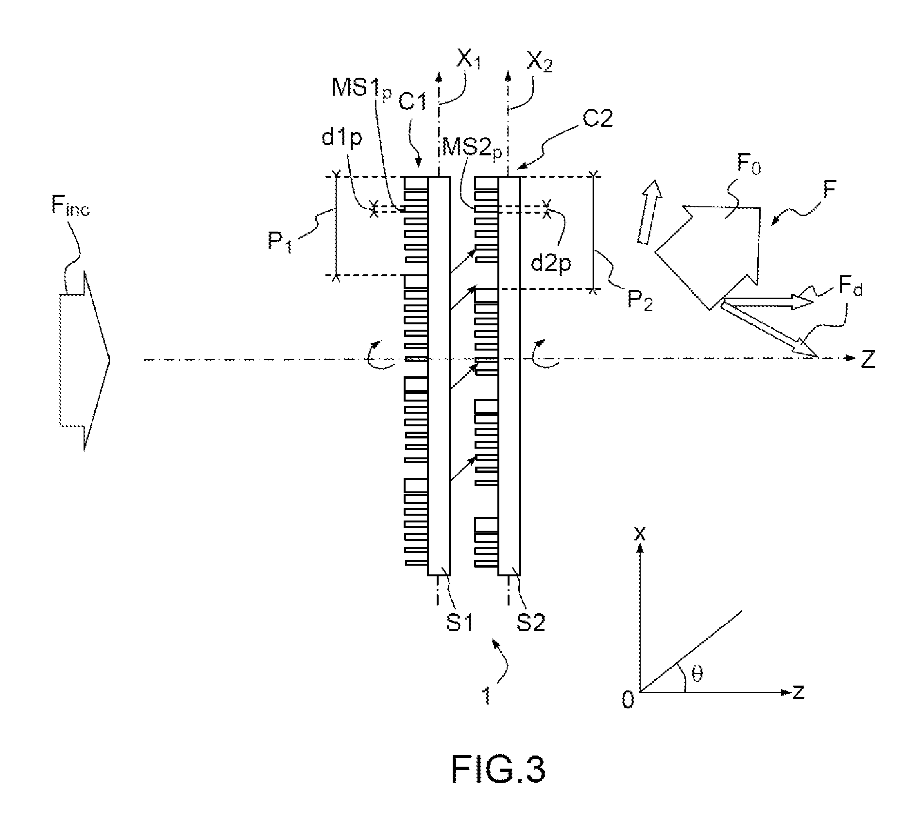
[0031]There is proposed, according to one aspect of the invention, a configurable deflection system for an incident microwave frequency beam exhibiting a wavelength contained in a band of wavelengths corresponding to the microwave frequencies, comprising:

[0032]a first and a second diffractive dielectric component suitable for each performing a rotation about a rotation axis Z,

[0033]the deflection system being suitable for generating a microwave frequency beam by diffraction of the incident microwave frequency beam on the first and second components, the microwave frequency beam being oriented according to an angle that is a function of the angular positioning between the first and the second diffractive components,

[0034]the first and second components respectively exhibiting a first and second periodic structure of first and second periods according to a first and second axis, the first and second structures respectively comprising a plurality of first and second primary microstruct...


PUM


Abstract

A configurable deflection system for an incident microwave frequency beam exhibiting a wavelength contained in a band of wavelengths corresponding to the microwave frequencies, comprising: a first and a second diffractive dielectric component suitable for each performing a rotation about a rotation axis Z, the deflection system being suitable for generating a microwave frequency beam by diffraction of the incident microwave frequency beam on the first and second components, the microwave frequency beam being oriented according to an angle that is a function of the angular positioning between the first and said second diffractive components, the first and second components respectively exhibiting a first and second periodic structure of first and second periods according to a first and second axis, the first and second structures respectively comprising a plurality of first and second primary microstructures formed respectively on a first and second substrate of first and second substrate refractive indices.

Description

FIELD OF THE INVENTION[0001]The invention relates to the processing of microwave frequency waves, and in particular the deflection of a microwave frequency beam. More specifically, the invention relates to a configurable deflection system.STATE OF THE ART[0002]The invention applies to the processing of a microwave frequency beam, corresponding to frequencies lying between 300 MHz and 300 GHZ, with typical wavelengths of 1 mm to 1 m.[0003]A number of applications require the capability to control the direction in which the beam is transmitted and / or received. This property is called aiming.[0004]For the aiming, the antenna has to be configured to transmit / receive a wave in a given direction of space. For example, these days, in the field of telecommunications, there is an increasing need to have to redirect an antenna, following the updating of the coverage of the land. For example, each time an antenna is removed, there follows a repositioning of the neighboring antennas. Moreover, ...

Claims


Application Information

Patent Timeline
Patent Type & Authority Applications(United States)
IPC IPC(8): H01Q15/10H01Q3/14
CPCH01Q15/10H01Q3/14
Inventor LEE-BOUHOURS, MANE-SI LAUREBRUS, ANTOINELOISEAUX, BRIGITTEDOUSSET, THIERRYRENARD, CHRISTIAN
Owner THALES SA
Why Eureka
Try Eureka