Method for balancing the voltage of battery cel

a technology of battery ce and voltage, applied in the direction of battery/cell control arrangement, electric devices, battery/fuel cell propulsion, etc., can solve the problem of limiting the capacity and lifetime of the battery pack as a whole, long overall battery cell balancing time, and small differences in capacity, state of charge, etc. problem, to achieve the effect of fast less power, and high discharge rate of electrical storage system

Active Publication Date: 2016-01-07
VOLVO LASTVAGNAR AB
View PDF4 Cites 7 Cited by
  • Summary
  • Abstract
  • Description
  • Claims
  • Application Information

AI Technical Summary

Benefits of technology

[0011]The at least one large electrical machine may be an electrical traction machine or the main electrical generator of the hybrid electric vehicle. These electrical machines normally represent the most powerful electrical machines on a hybrid electric vehicle, and consequently have the potential to enable the fastest discharge rate of the electrical storage system when operated. The at least one large electrical machine may alternatively be any of an electric machine driving a vehicle and/or cargo air conditioning system, an electrical, machine driving an air compressor unit, an electrical machine driving a cooling fan, or an electrical machine driving a hydraulic pump of a hydraulic system. These electrical machines are normally less powerful than the electrical traction machine or the main electric& generator of the hybrid electric vehicle, but have instead the advantage of enabling accumulation of the discharged electrical energy. Accumulation, i.e. recuperation, of the discharged electrical energy from the electrical storage system may for example be realised by lowering/increasing the temperature of the cargo compartment a driving cabin, or charging the air storage container with compressed air, or charging a hydraulic accumulator. In this way, energy that would otherwise be wasted can come to use and replace energy that otherwise would have had to be generated.
[0012]Discharge of the electrical storage system (ESS) may he realised by setting a combustion engine of the hybrid electric vehicle in a non-combustion mode and rotating a crankshaft of the combustion engine by means of the electrical traction machine or the main electrical generator, depending on the powertrain layout of the hybrid electric vehicle. The electrical traction machine or the main electrical generator are nearly always the largest electrical machines in a hybrid electric vehicle, and using any of them for driving the crankshaft of the combustion engine in a non-combustion mode, i.e. cranking, is one of the most power requiring activities in a vehicle. Thus a high discharge rate of the electrical storage system can be obtained. The method may additionally comprise actuating an exhaust brake and/or an engine compression brake for increasing the torque required to rotate the crankshaft and thereby increasing the discharge rate of the electrical storage system.
[0013]The electrical storage system may comprise a cooling system that is operated during the discharge of the electrical storage system. A high discharge rate generally results in high beat generation from the electrical storage system. In many vehicles, the cooling system of the electrical storage system is operated by a separate electrical motor driving a pump for circulating a heat conducting liquid, such as water. Alternatively, the pump may be mechanically powered via the crankshaft when the engine t

Problems solved by technology

However, no two cells are identical—there are always slight differences in for example capacity, state of charge, and self-discharge rate.
The capacity and lifetime of the weakest cell limit the capacity and lifetime of the battery pack as a whole.
In order to limit the temperature increase, the discharge power has to be low which in turn leads to an overall long battery cell balancing time.
A high discharge rate generally results in high beat generation from the electr

Method used


Image

  • Method for balancing the voltage of battery cel
  • Method for balancing the voltage of battery cel
  • Method for balancing the voltage of battery cel

Examples


Embodiment Construction

[0029]Various aspects of the disclosure will hereinafter be described in conjunction with the appended drawings to illustrate and not to limit the disclosure. Like designations denote like elements, and variations of the described aspects are not restricted to the specifically shown embodiments, but are applicable on other variations of the disclosure.

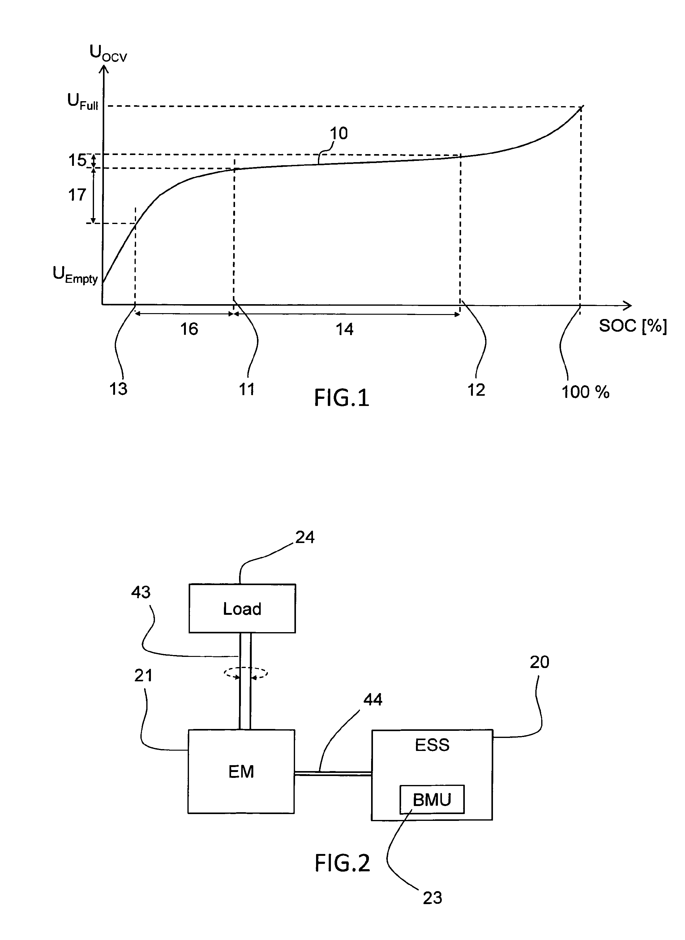
[0030]FIG. 1 shows a graph of the output open circuit voltage OCV as a function of the chemical state of charge SOC of a typical electrochemical cell, which graph is also commonly referred to as “voltage discharge curve”. The electrochemical cell may preferably be a lithium cell. The electrical storage system may comprise at least 100 series-connected electrochemical cells and preferably at least 150 series-connected cells, for example lithium cells. The electrical storage system may also be referred to as a battery pack and the output voltage of the electrical storage system equals the accumulated output voltage of each cell of a comm...


PUM


Abstract

A method is provided for balancing the voltage of multiple series-connected electrochemical cells of an electrical storage system of a hybrid electric vehicle. The method includes discharging the electrical storage system by operating at least one large electrical machine of the vehicle at vehicle standstill until the state of charge of the electrical storage system or the cell having the lowest state of charge has reached a predetermined level, and subsequently balancing the voltage of the cells.

Description

BACKGROUND AND SUMMARY[0001]This disclosure relates to a method for balancing the voltage of multiple series-connected electrochemical cells of an electrical storage system of a hybrid electric vehicle. The method comprises the step of discharging the electrical storage system before cell balancing. The disclosure also relates to a hybrid electric vehicle comprising an electrical storage system, wherein a battery management unit of the electrical storage system is configured to discharge the electrical storage system before cell balancing. The disclosure is particularly advantageous in the field of electrical storage systems for heavy hybrid vehicles, such as trucks, buses, construction vehicles, or the like.[0002]The electrical storage systems in electric and hybrid electric vehicles commonly comprise battery packs of multiple series-connected electrochemical cells, typically hundreds of lithium cells. However, no two cells are identical—there are always slight differences in for e...

Claims


Application Information

Patent Timeline
IPC IPC(8): B60L11/18B60L50/16B60L50/30H02J7/00
CPCH02J7/0016B60L11/1866H02J7/0014B60L1/003B60L1/006B60L3/12B60L7/20B60L15/20B60L15/2009B60L2200/18B60L2200/36B60L2240/34B60L2240/423B60L2240/545B60L2240/547B60L2240/549B60L2240/80B60L2260/44Y02T10/72B60L50/16B60L50/30B60L50/51B60L58/13B60L58/22H02J2310/48Y02T10/64Y02T10/7072B60L3/0046Y02T10/70
Inventor SMIDEBRANT, TOBIASLENNEVI, JERKER
Owner VOLVO LASTVAGNAR AB
Why Eureka
Try Eureka