Polycondensation vacuum reaction system for flame-retardant slice production and production process

A reaction system and polycondensation technology, applied in pressure vessels/vacuum vessels, chemical/physical/physicochemical fixed reactors, pressure vessels used in chemical processes, etc., can solve the problem of low material reaction rate, low material film forming efficiency, Low heat exchange efficiency and other issues, to achieve the effect of improving the film forming effect, improving the film forming efficiency and increasing the film forming area

Pending Publication Date: 2022-07-29
浙江安吉骏逸新材料科技有限公司
View PDF7 Cites 0 Cited by
  • Summary
  • Abstract
  • Description
  • Claims
  • Application Information

AI Technical Summary

Problems solved by technology

[0005] The purpose of the present invention is to address some of the deficiencies of the prior art. The present invention discloses a polycondensation vacuum reaction system for the production of flame-retardant slices. By setting a hollow coil spring for heat exchange and cooperating with driving the hollow coil spring to wind up or The unwinding first tube and the second tube can realize sufficient extrusion and mixing of materials and improve heat exchange efficiency and material film forming efficiency, thereby allowing the by-products of the polymerization reaction to fully overflow, increasing the rate of polycondensation reaction and the yield of products. It solves the problem of low heat exchange efficiency and low material reaction rate caused by the low heat exchange efficiency and low film formation efficiency of the material in the conventional reaction system, which makes the required amount of product slow to obtain question question

Method used


Image

  • Polycondensation vacuum reaction system for flame-retardant slice production and production process
  • Polycondensation vacuum reaction system for flame-retardant slice production and production process
  • Polycondensation vacuum reaction system for flame-retardant slice production and production process

Examples


Embodiment 1

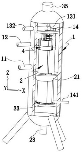
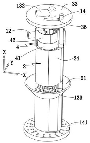
[0073] like Figure 1-2 , 9, the present invention provides a kind of polycondensation vacuum reaction system for flame retardant chip production, comprising:

[0074] The kettle body 1 is provided with a vacuum exhaust pipe 11;

[0075] The hollow coil spring 2 arranged in the kettle body 1;

[0076] A feeding pipe 12 extending into the kettle body 1 and used for feeding material to the upper end of the hollow coil spring 2 so that the material flows down the side wall of the hollow coil spring 2;

[0077] The first tube 13 and the second tube 14 are respectively communicated with both ends of the hollow coil spring 2 and cooperate to drive the hollow coil spring 2 to zoom in and out to promote the heat exchange between the fluid and the material in the hollow coil spring 2 .

[0078] Further, the lower end of the kettle body 1 is provided with a discharge port 15, and the vacuum exhaust pipe 11 is connected to the vacuum pump; the first pipe 13 is located at the center of ...

Embodiment 2

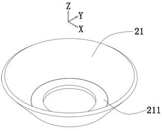
[0095] like Figure 1-11 As shown, the same or corresponding components as those in the first embodiment are given the corresponding reference numerals as in the first embodiment. For the sake of brevity, only the points of difference from the first embodiment are described below. The difference between the second embodiment and the first embodiment is: Figure 4 , 8 , 9, a plurality of the hollow coil springs 2 with different inner diameters are concentrically sleeved, and the plurality of hollow coil springs 2 communicate with the same first tube 13 and the second tube 14.

[0096] It should be noted that a plurality of hollow coil springs 2 are concentrically sleeved, each hollow coil spring 2 has a different inner diameter, and the gaps between adjacent hollow coil springs 2 are the same or close. The same first tube 13 and the second tube 14 are connected to simplify the arrangement structure; compared with the previous embodiment or the prior art, a plurality of hollow...

Embodiment 3

[0129] like Figure 12 As shown, the present embodiment provides a production process for flame retardant chips, comprising the following steps:

[0130] Step 1, the first tube 13 continuously feeds the fluid into the hollow coil spring 2 and causes the fluid to flow out from the second tube 14;

[0131] Step 2. After the fluid is introduced into the hollow coil spring 2, the material is dropped from the top of the hollow coil spring 2. By controlling the amount of material input, the material flows down in the form of a film along the side wall of the hollow coil spring 2. In order to realize the heat exchange with the fluid in the hollow coil spring 2, in order to realize the sufficient overflow of reaction by-products;

[0132] Step 3, while step 2 is being carried out, the by-product overflowing from the side wall of the hollow coil spring 2 in the kettle body 1 is evacuated through the vacuum exhaust pipe 11;

[0133] Step 4. At the same time as step 2, the first tube 13 ...


PUM


Abstract

The invention relates to the technical field of flame-retardant slice production, in particular to a condensation polymerization vacuum reaction system for flame-retardant slice production and a production process. The hollow coil spring is arranged in the kettle body; the feeding pipe extends into the kettle body and is used for conveying materials to the upper end of the hollow coil spring so as to enable the materials to flow downwards along the side wall of the hollow coil spring; the first pipe and the second pipe are respectively communicated with two ends of the hollow coil spring and are matched to drive the hollow coil spring to contract and contract so as to promote heat exchange between fluid in the hollow coil spring and materials; the device has the advantages of high heat exchange efficiency, high polymerization reaction rate, high byproduct discharge rate and high product yield.

Description

technical field [0001] The invention relates to the technical field of flame retardant chip production, in particular to a polycondensation vacuum reaction system and a production process for the production of flame retardant chips. Background technique [0002] The reaction system is widely used in the fields of petroleum, chemical industry, rubber, pesticide, dye, medicine and food. , decomposition pot, polymerization kettle, etc.; the materials are generally carbon-manganese steel, stainless steel, zirconium, nickel-based (Hastelloy, Monel, Inconel) alloys and other composite materials; [0003] A Chinese invention patent with the authorization announcement number of CN102492127B, including setting a tube sheet in the vertical shell, connecting the tube sheet to the tube, setting a material distributor at the upper end of the tube, and between the upper end of the tube and the material distributor There is an annular gap; a feed port is set at the top of the vertical she...

Claims


Application Information

Patent Timeline
Patent Type & Authority Applications(China)
IPC IPC(8): B01J19/18B01J3/03B65H75/38B65H75/44
CPCB01J19/18B01J3/03B65H75/38B65H75/4481B01J2219/00081
Inventor 朱林军高永祥
Owner 浙江安吉骏逸新材料科技有限公司
Why Eureka
Try Eureka