Charged Particle Beam Apparatus, Stage Controlling Method, and Stage System

a particle beam and charge technology, applied in electrical apparatus, electric discharge tubes, nuclear engineering, etc., can solve the problems of insufficient increase, inability to adjust current amount, heat generation, etc., and achieve the effect of reducing temperature change and improving sample positioning accuracy

Active Publication Date: 2016-01-07
HITACHI HIGH-TECH CORP
View PDF3 Cites 21 Cited by
  • Summary
  • Abstract
  • Description
  • Claims
  • Application Information

AI Technical Summary

Benefits of technology

[0008]Thus, as described in JP-A-2003-309062, it is conceivable that the stage is idling when the apparatus is not running and a temperature while the stage being driven is maintained. However, in this method, since the stage is operated in addition to an operation time required for original observation or inspection, a service life of a guide of the stage, a bending wiring, and the like becomes shorter.
[0009]An object of the invention is to provide an apparatus in which a temperature change between a driving state and a static state of the apparatus is reduced and a positioning accuracy of a sample is improved without affecting a service life of the apparatus.
[0011]According to the invention, it is possible to reduce the temperature change between the driving state and the static state of the apparatus without affecting a service life of the apparatus. Thus, the positioning accuracy of the sample can be improved. Objects, configurations, and effects other than the above description will become apparent from the following descriptions of embodiments.

Problems solved by technology

However, in a case of a method disclosed in JP-A-2004-111684, a current amount cannot be adjusted only in a range enough to keep a static state of the stage, that is, in a range in which a driving force of the stage does not exceed a static friction force.
In this method, the current amount cannot be sufficiently increased, and heat generation when the stage is operated and heat generation when the stage stops may not be able to be the same extent.
However, in this method, since the stage is operated in addition to an operation time required for original observation or inspection, a service life of a guide of the stage, a bending wiring, and the like becomes shorter.

Method used


Image

  • Charged Particle Beam Apparatus, Stage Controlling Method, and Stage System
  • Charged Particle Beam Apparatus, Stage Controlling Method, and Stage System
  • Charged Particle Beam Apparatus, Stage Controlling Method, and Stage System

Examples


first example

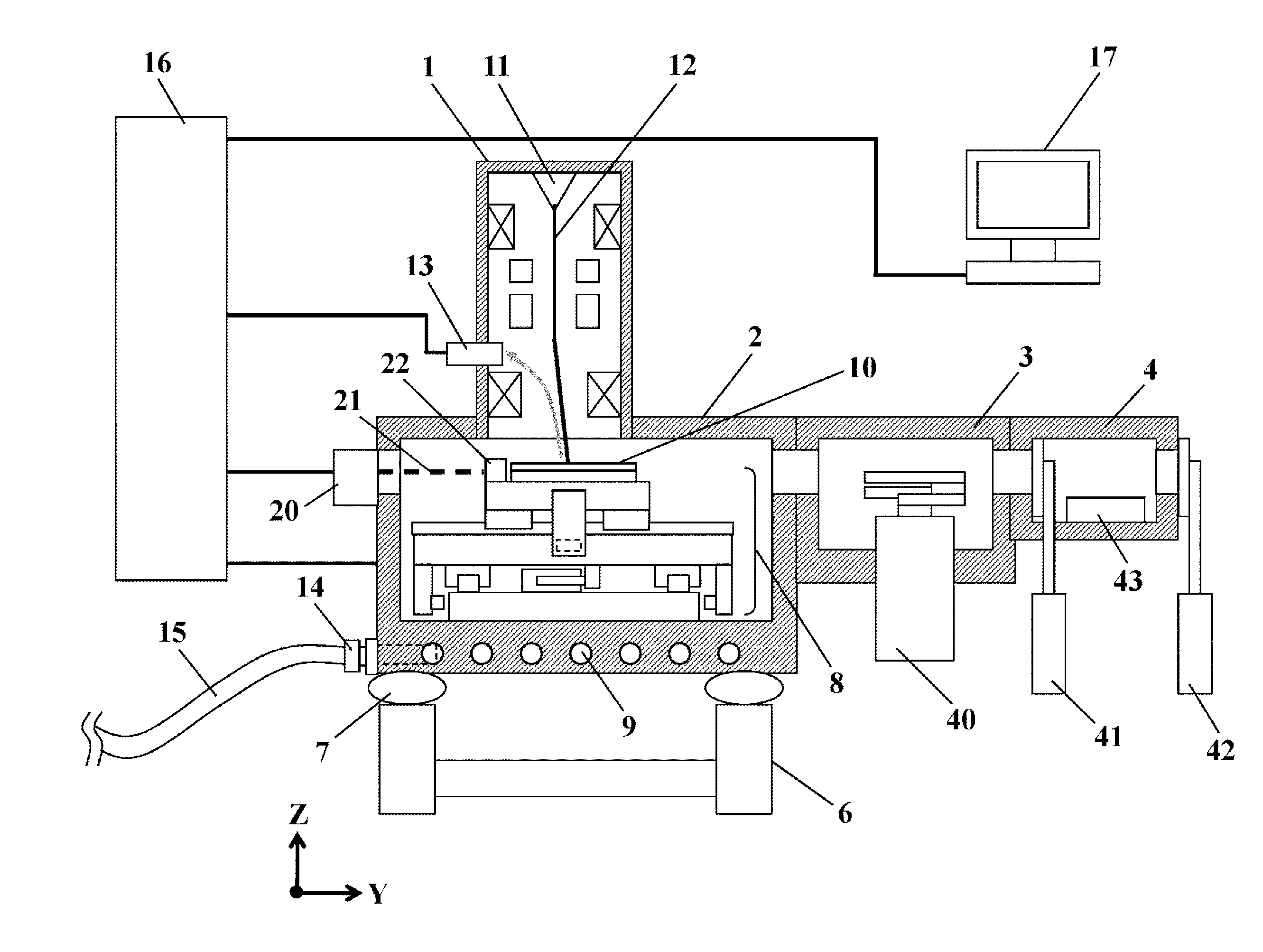
[0041]FIG. 1 schematically illustrates an entirety of an inspection apparatus of the example.

[0042]Mounts 7 for damping vibration of a floor are installed on a pedestal 6 provided on the floor and the mounts 7 support a sample chamber 2 that is a vacuum vessel. A column 1 that controls an electron beam 12 to be generated and to scan the sample is installed in an upper portion of the sample chamber 2. The column 1 includes a deflector that deflects the electron beam 12 so as to scan the sample or an objective lens that converges on the electron beam 12 on the sample in addition to an electron source 11 generating the electron beam 12. In addition, the column may include other various lens or apertures and a configuration of a charged particle optical system is not limited to the examples. In addition, the column 1 is provided with a detector 13 for detecting secondary charged particles such as secondary electrons or reflective electrons obtained by applying the electron beams to the ...

second example

[0088]Next, as a second example, a control method in which a temperature sensor is mounted on the stage and information thereof is fed back to the command value during the warming up operation will be described with reference to FIGS. 19 and 20. Hereinafter, a description regarding the same portions as the first example will be omitted.

[0089]In the first example, the operation rate of the stage is predicted and the current of the motor is set, but if the frequency of the inspection is greatly changed by time or if a recipe in which the operation rate of the stage is high and a recipe in which the operation rate of the stage is low are mixed in one inspection, it is difficult to accurately predict the heat amount of the motor. It is easy to maintain a constant temperature by mounting the temperature sensor on the motor and controlling the current amount based on the information of the temperature even if the operation rate of the stage is different.

[0090]In the example, a structure i...

third example

[0094]Next, a third example will be described with reference to FIGS. 23 and 24. In the example, an example is described in which the warming up operation described in the first and second examples is performed in each position by moving the stage by a predetermined distance for each predetermined time.

[0095]First, a structure of a linear motor is described. Typically, the linear motor is often configured of a coil of three phases (U phase, V phase, and W phase), and a plurality of same phases are used as each phase is one movable element. In FIG. 23, the movable element is indicated in which two coils of each phase are arranged. Linear motor movable elements (30 and 32) are configured of a total six coils consisting of U phase coils 35, V phase coils 36, and W phase coils 37. In the linear motor fixing element, a plurality of magnets are arranged such that adjacent magnets generate a magnetic field having different directions to each other.

[0096]FIG. 24 illustrates how the current ...


PUM


Abstract

A stage system includes a stage that holds an object, a linear motor mechanism that moves the stage by a thrust force generated by a current flowing through the coil, and a control section that controls the current flowing through the coil. The current flowing through the coil in a state where the stage is maintained in the static state be greater than a minimum current amount required for generating the thrust force greater than a maximum static friction force of the stage with respect to the guide rails.

Description

BACKGROUND OF THE INVENTION[0001]The present invention relates to a stage control method for holding an object and a stage system using the stage control method. Particularly, the invention relates to a charged particle beam apparatus such as an electron microscope, an ion beam machining / observation apparatus, and the like.[0002]In recent years, integration of semiconductor products has been improved more and more and higher definition of a circuit pattern thereof has been required. Various inspection means for the purpose of quality control and a yield increase have been used in a sample such as a wafer on which the circuit pattern is formed. For example, there is a SEM type inspection apparatus using an optical type inspection apparatus or a scanning type electron microscope (SEM) for inspecting foreign matters or defects of the wafer by applying light. Furthermore, a scanning type electron microscope (hereinafter, referred to as a length measurement SEM) for measuring a dimension...

Claims


Application Information

Patent Timeline
Patent Type & Authority Applications(United States)
IPC IPC(8): H01J37/20H01J37/22
CPCH01J37/20H01J2237/2602H01J2237/20278H01J37/22H01J2237/20221
Inventor MIZUOCHI, MASAKINISHIOKA, AKIRANAKAGAWA, SHUICHIOGAWA, HIRONORI
Owner HITACHI HIGH-TECH CORP
Why Eureka
Try Eureka