Reconfigurable radio direction finder system and method

a radio direction finder and reconfigurable technology, applied in direction finders, direction finders using radio waves, instruments, etc., can solve the problems of difficult configuration of frequency, radiation pattern and polarization independent of one another, and is not convenient in general, and achieves the effect of reducing the number of radiation sources

Inactive Publication Date: 2016-01-07
QATOR FOUND FOR EDUCATION SCI & COMMUNITY DEV
View PDF5 Cites 23 Cited by
  • Summary
  • Abstract
  • Description
  • Claims
  • Application Information

AI Technical Summary

Problems solved by technology

Direction finding over a wide operating frequency range requires different sizes of antenna arrays, which is typically not convenient due to the actual physical implementation of such systems and / or degradation in performance if proper requirements between antenna space and the wavelength of the operation frequency are not met.
Thus, the overall goal in using a reconfigurable antenna is to control change of the current distribution around the antenna, which leads to altering the radiated far field.
The selection process is based on several performance parameters, such as power consumption, directivity, bandwidth operating frequency and the like, in addition to design constraints, such as antenna size, fabrication costs, etc.
It is very difficult to configure frequency, radiation pattern and polarization independent of one another, as changing one characteristic will change the others.

Method used


Image

  • Reconfigurable radio direction finder system and method
  • Reconfigurable radio direction finder system and method
  • Reconfigurable radio direction finder system and method

Examples


Embodiment Construction

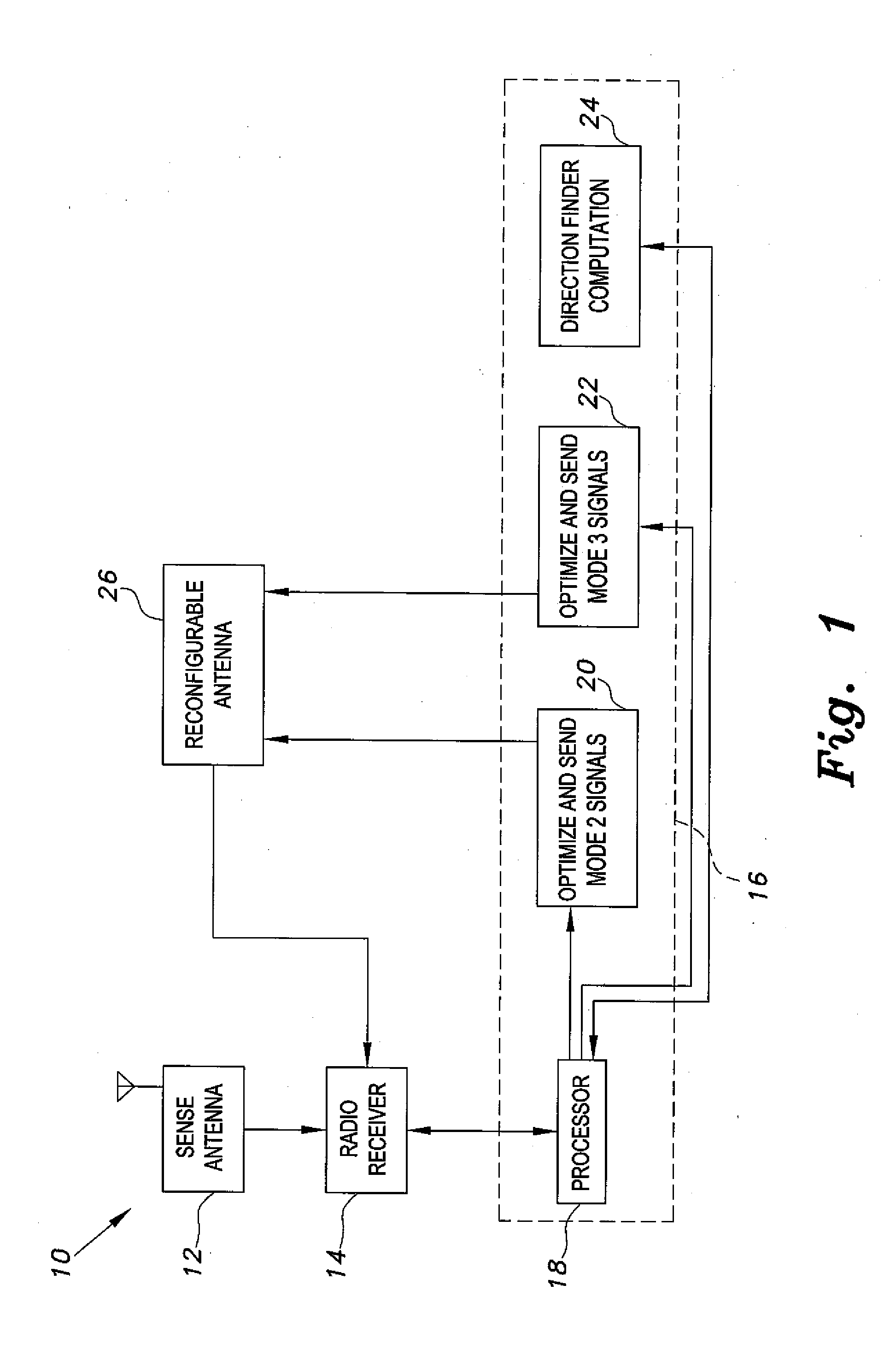
[0025]As illustrated in the block diagram of FIG. 1, the reconfigurable radio direction finder system 10 operates in three stages or modes. In the first mode, a receiver senses a radio spectrum and detects signals and their bandwidth via a wideband antenna detection system including a sense antenna 12. Wideband antennas for sensing radio frequency signals and their bandwidths are known in the art, and it should be understood that wideband antenna detection system sense antenna 12 can utilize various suitable types of wideband antennae coupled with a suitable type of radio receiver 14, as can depend on the use or application, for example. The wideband antenna could be a separate wideband antenna or a reconfigurable antenna configured for a wide frequency range operation, for example. The detected signal of interest is initially defined in terms of its frequency range, bandwidth and polarization. This information is fed to a controller 16, which operates as a reconfiguring unit or a s...


PUM


Abstract

The reconfigurable radio direction finder system and method uses a reconfigurable antenna to electronically cycle through a plurality of different antenna configurations to determine a signal direction. Specifically, the reconfigurable antenna is cycled through N different antenna configurations, where N is an integer greater than one, where each antenna configuration has a pointing direction associated therewith defined by an elevation angle θn of an n-th antenna configuration, where n is an integer between 1 and N, and an azimuthal angle φn of the n-th antenna configuration. A received signal strength of the radio signal is measured for each of the antenna configurations as a power output of the n-th antenna configuration, Pn. A spherical weighted directional mean vector (XDF, YDF, ZDF) is then estimated for the radio signal asXDF=1NΣn=1NPncos(φn)sin(θn),YDF=1NΣn=1NPnsin(φn)sin(θn)andZDF=1NΣn=1NPnsin(θn).

Description

BACKGROUND OF THE INVENTION[0001]1. Field of the Invention[0002]The present invention relates to direction finding of radio frequency signals, and particularly to a system and method utilizing a reconfigurable antenna to estimate signal direction.[0003]2. Description of the Related Art[0004]Conventional radio direction finder systems are typically phased array systems. Phased antenna array systems are based on a fixed antenna pattern of each antenna element in the antenna array. Arriving signals from different antennas are weighted to create proper beam forming in the direction of arrival. A phased array depends on the antenna geometry and whether the particular antenna array can estimate both angles (i.e., azimuth and elevation). For example, a horizontal linear array can be used to estimate the azimuth angles but not the vertical angles, and the reverse is true for a vertical linear array. The planar, circular, spherical or alike antenna array configurations may measure both the a...

Claims


Application Information

Patent Timeline
Patent Type & Authority Applications(United States)
IPC IPC(8): H01Q3/24G01S3/38
CPCG01S3/38H01Q3/24G01S3/14G01S3/72H01Q21/065
Inventor EL-SALLABI, HASSAN MOHAMEDABDULLAH, MOHAMED MAHMOUDQARAQE, KHALID ALIHUFF, GREGORY H.CHAMBERLAND-TREMBLAY, JEAN-FRANCOIS
Owner QATOR FOUND FOR EDUCATION SCI & COMMUNITY DEV
Why Eureka
Try Eureka