
Electric motor, generator and commutator system, device and method

a technology of commutator system and electric motor, which is applied in the direction of windings, dynamo-electric components, and commutation monitoring, etc., can solve the problems of rotors that are not always perfect, not always easy to fit, and various types of inefficiency in ac electric motors and other devices

Inactive Publication Date: 2016-01-07
TURBOROTO
View PDF1 Cites 39 Cited by
  • Summary
  • Abstract
  • Description
  • Claims
  • Application Information

AI Technical Summary

Benefits of technology

This patent describes two types of electric motor systems: a direct current (DC) electric motor system and an alternating current (AC) induction electric motor system. Both systems include a stator with at least three coils that produce a rotating magnetic field when induced by electric current. The stator and coils are configured to capture energy released from a collapsing magnetic field on one step of a commutation sequence, using the next step's coils. These technical effects enhance the efficiency of electric motor systems by optimizing energy usage and reducing energy waste.

Problems solved by technology

Rotors often, but not always, fit inside openings that are often in the center of the stator body.
This is not entirely always easy.
The jagged, step function type nature of the AC current provided by a VFD creates Total Harmonic Distortion (THD) effects, and this THD effects in turn create various types of inefficiencies and other problems in AC electric motors and other devices.
Thus, for example, when a typical VFC driver switches between producing 2 KiloHertz (kHz) to 15 kHz AC current, and is used to drive an AC motor, at the higher frequency, there are typically greater VFD power switching losses as well as a greater AC skin effects on the motor winding.
This causes both waste energy and creates unwanted heat.
However AC motors are often not as strong as DC motors.
This limits the maximum starting torque that an AC motor can exert.
An additional problem with AC motors is that the varying magnetic field causes induction resistance which, relative to DC motors, further restricts current flow at the maximum supply voltage.
This further limits the strength of the AC motor coil's magnetic fields, and thus further limits maximum torque, especially at high rotations per minute (RPM).
Another problem with AC motors is that AC skin effect (AC tends to travel along the outside “skin” of a wire, rather than inside the wire) further resists current flow at a high frequency which again limits its performance.
Other problems associated with AC controllers, such as total harmonic distortion (THD), which converts into heat in the stator core, waste energy and reduce the motor's power density for a given motor frame size.

Method used


Image

  • Electric motor, generator and commutator system, device and method
  • Electric motor, generator and commutator system, device and method
  • Electric motor, generator and commutator system, device and method

Examples


Embodiment Construction

[0056]In contrast to AC motors, DC electrical motors don't have a “natural commutator”. To operate a DC electrical motor, the DC current passing through the various coils of the DC motor must be varied using various types of commutator devices. In some DC electric motor designs, the stator may incorporate either permanent magnets or non-switched electromagnets (e.g., non switched stator coils), and instead the magnetic field of the rotor may be varied by a function of time, usually by switching the direction of current flowing through the windings of the various rotor coils.

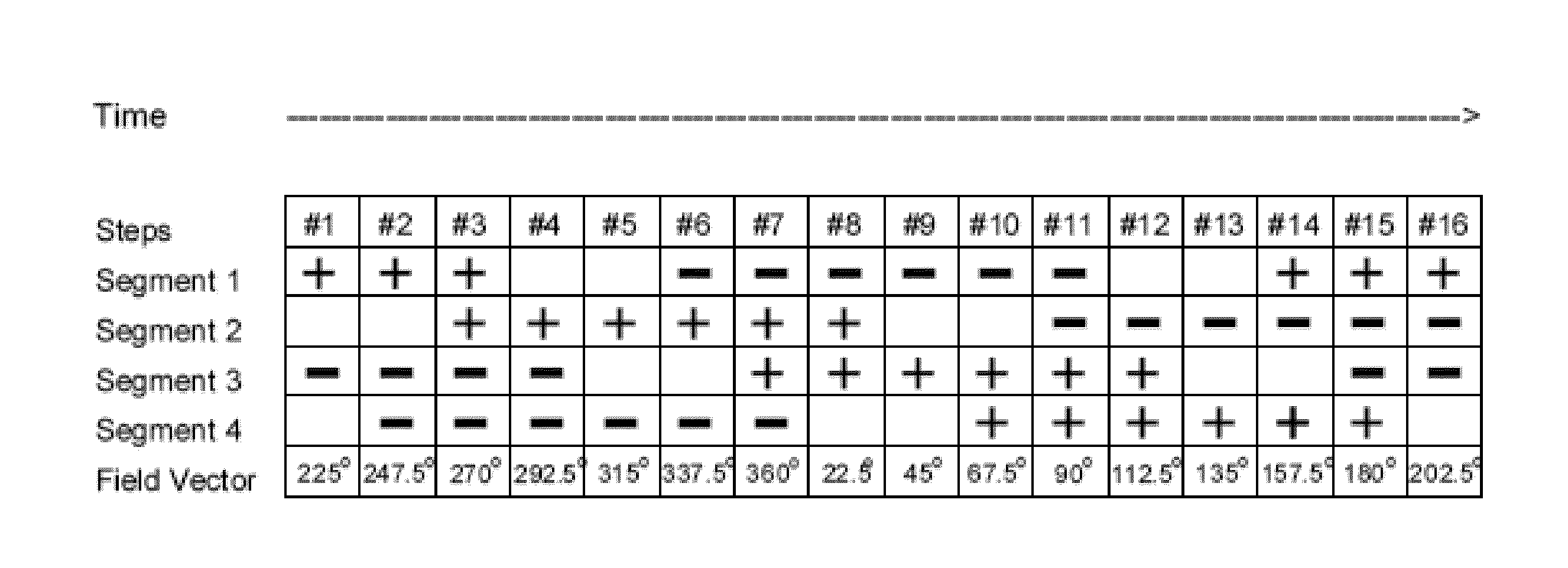
[0057]In some alternative DC motor designs, a rotating magnetic field is generated on the DC electric stator instead. In these designs, the motor stator generally comprises various coils (each coil usually formed from multiple wire windings). The motor stator can be operated by sequentially switching or commutating the direction of the current flowing through the windings of the various motor stator coils in a ma...


PUM


Abstract

A direct current (DC) electric motor assembly with a closed type overlap stator winding which is commutated with a timed commutating sequence that is capable of generating a stator rotating magnetic field. The coil overlap of the winding and a timed commutation sequence are such that the current in each slot of the stator is additive and when a previous magnetic pole collapses according to a commutation sequence; the energy released by that previous collapsing magnetic field is captured to strengthen the next magnetic field on the commutation sequence schedule. Electrical currents produced by the collapsing magnetic fields flow to low electric potential and add or subtract to the DC current provided by the commutator thus promoting formation of the next magnetic on commutation schedule. When used with a suitable commutator and rotor, the electric motor assembly provides a true brushless high torque speed controlled Real Direct Current (RDC) motor that operates with higher efficiency and higher power density.

Description

CROSS REFERENCE TO RELATED APPLICATIONS[0001]This application claims the priority benefit of U.S. Provisional Patent Application No. 62 / 014,114, titled “True Brushless DC Motor, Generator and Commutator”, and filed on Jun. 19, 2014; the entire contents of this application are incorporated herein by reference.FIELD OF THE INVENTION[0002]This invention is in the field of electric motors, generators and commutator systems.BACKGROUND OF THE INVENTION[0003]The direct current (DC) electric motor was invented in the early 1800's, and the alternating current (AC) electric motors were invented about 50 years later in the later 1800's. Since then both types of electric motors have become highly developed and are used to provide mechanical force for a wide variety of different applications.Brief Review of Basic Electromagnetism and Electric Motor Design[0004]Ampere's Law describes the generation of a magnetic field in the presence of an electric current. Magnetic fields produced via Ampere's L...

Claims


Application Information

Patent Timeline
IPC IPC(8): H02K3/28H02K3/12H02K11/00
CPCH02K3/28H02K11/0015H02K3/12H02K23/28H02P6/12
Inventor LI, PING
Owner TURBOROTO
Features
  • Generate Ideas
  • Intellectual Property
  • Life Sciences
  • Materials
  • Tech Scout
  • Unparalleled Data Quality
  • Higher Quality Content
  • 60% Fewer Hallucinations
Learn More