Radio-frequency module
a radio frequency module and module technology, applied in waveguide type devices, frequency selective two-port networks, amplifier modifications to reduce non-linear distortion, etc., can solve the problems of reduced radio frequency modules, ground electrodes that cannot perform their functions properly, and high-output radio frequency output, etc., to achieve excellent rf characteristics and excellent rf characteristics
- Summary
- Abstract
- Description
- Claims
- Application Information
AI Technical Summary
Benefits of technology
Problems solved by technology
Method used
Image
Examples
first embodiment
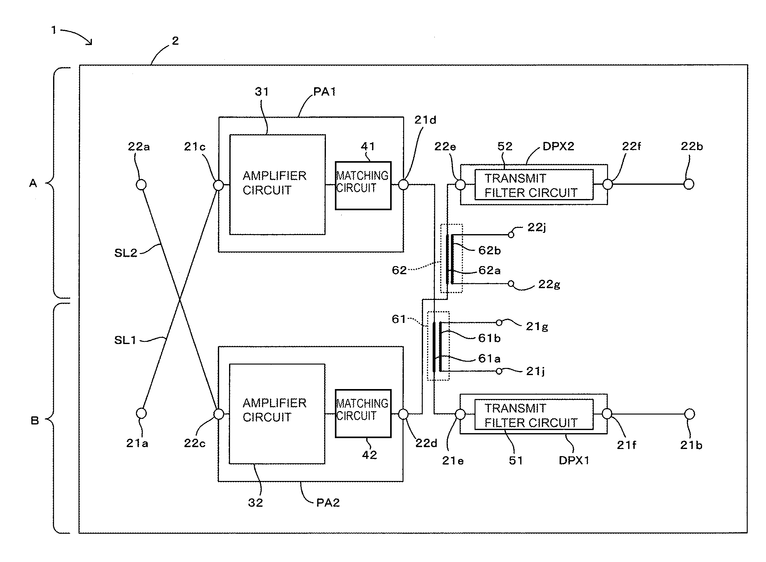
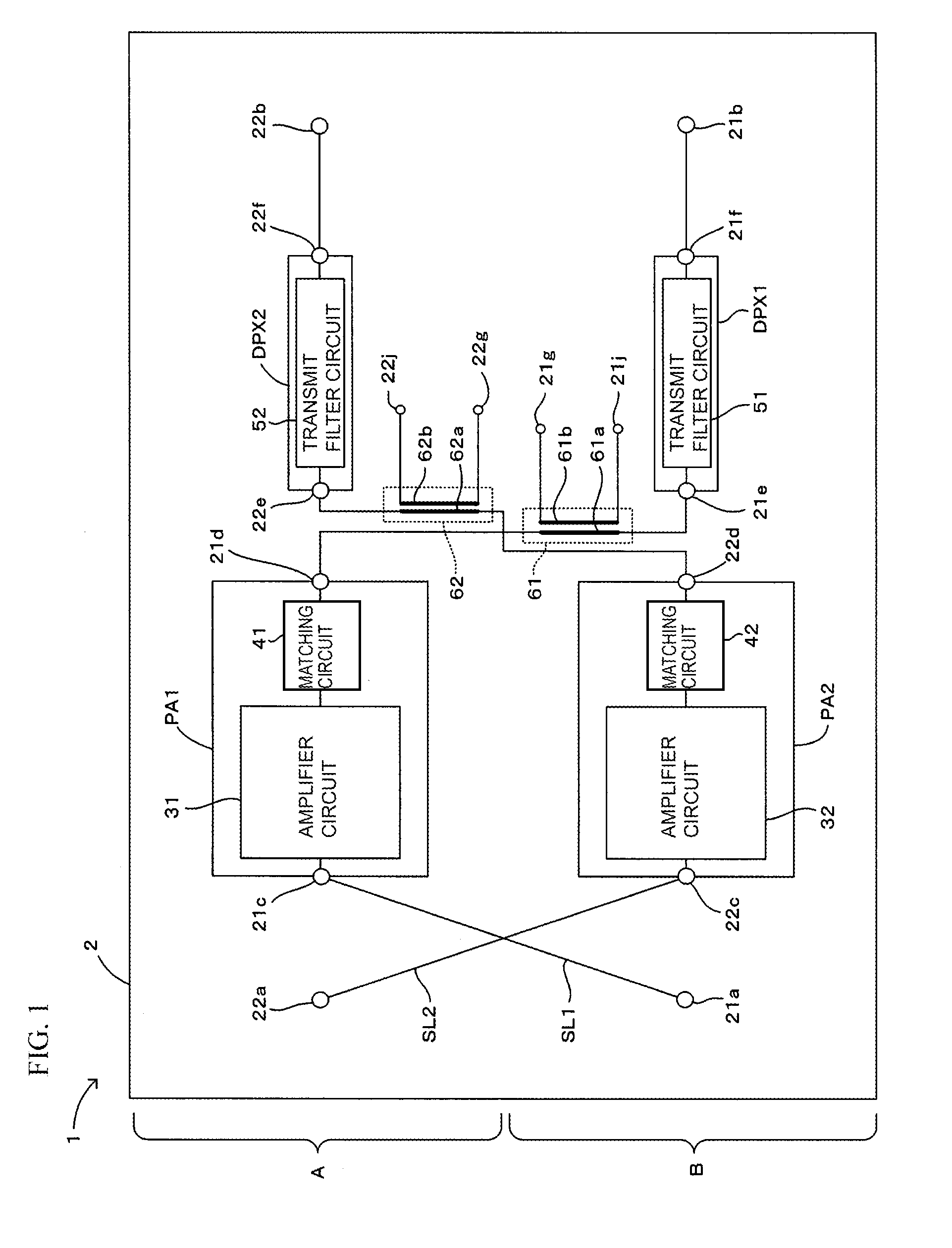
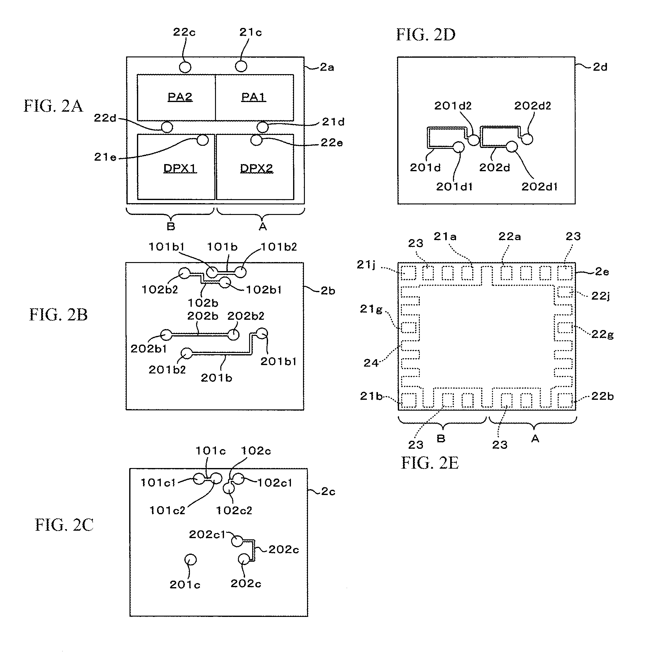
[0041]A first embodiment of a radio-frequency module according to the present disclosure will be described below with reference to FIGS. 1 through 5. FIG. 1 is a diagram illustrating the first embodiment of a radio-frequency module of the present invention. FIGS. 2A to 2E show plan views illustrating insulating layers of a multilayer substrate included in the radio-frequency module shown in FIG. 1. FIGS. 2A to 2E illustrate the different insulating layers. FIGS. 3A and 3B show diagrams illustrating a first signal path and a second signal path, as viewed from above. FIG. 3A illustrates the signal paths prior to amplifier circuits, and FIG. 3B illustrates the signal paths subsequent to the amplifier circuits.
[0042]FIGS. 4A and 4B show diagrams illustrating the power density of harmonic components contained in a radio-frequency signal output from the first signal path of the radio-frequency module shown in FIG. 1. FIG. 4A illustrates the power density of second harmonic components, and...
second embodiment
[0080]A second embodiment of a radio-frequency module of the present disclosure will be described below with reference to FIG. 6. FIG. 6 is a diagram illustrating the second embodiment of a radio-frequency module of the present invention.
[0081]A radio-frequency module 1a of this embodiment is different from the radio-frequency module 1 of the above-described first embodiment in the following configuration. As shown in FIG. 6, in an area where the first and second signal paths SL1 and SL2 intersect each other, a third filter circuit 71 is disposed in the first signal path SL1, and a fourth filter circuit 72 is disposed in the second signal path SL2. The other configurations of the second embodiment are similar to those of the above-described first embodiment, and thus, they are designated by like reference numerals and an explanation thereof will be omitted.
[0082]The third and fourth filter circuits 71 and 72 may be formed as band-pass filters, as in the above-described first and sec...
third embodiment
[0085]A third embodiment of a radio-frequency module of the present disclosure will be described below with reference to FIG. 7. FIG. 7 is a diagram illustrating the third embodiment of a radio-frequency module of the present invention.
[0086]A radio-frequency module 1b of this embodiment is different from the radio-frequency module 1 of the above-described first embodiment in the following configuration. As shown in FIG. 7, in an area prior to the first and second power amplifiers PA1 and PA2, the first and second signal paths SL1 and SL2 do not intersect each other. The other configurations of the third embodiment are similar to those of the above-described first embodiment, and thus, they are designated by like reference numerals and an explanation thereof will be omitted.
[0087]With this configuration, too, advantages similar to those of the above-described embodiment can be obtained.
[0088]In this embodiment, too, the above-described first and second directional couplers 61 and 62...
PUM
 Abstract
Description
Claims
Application Information
 - R&D
- Intellectual Property
- Life Sciences
- Materials
- Tech Scout
- Unparalleled Data Quality
- Higher Quality Content
- 60% Fewer Hallucinations
Browse by: Latest US Patents, China's latest patents, Technical Efficacy Thesaurus, Application Domain, Technology Topic, Popular Technical Reports.
© 2025 PatSnap. All rights reserved.Legal|Privacy policy|Modern Slavery Act Transparency Statement|Sitemap|About US| Contact US: help@patsnap.com


