
Display device

a display device and display technology, applied in the field of display devices, can solve the problems of display abnormalities, short circuits or signal disconnection, and relatively weak adhesion of the display device, and achieve the effect of favorable structural reliability

Inactive Publication Date: 2016-01-07
AU OPTRONICS CORP
View PDF2 Cites 5 Cited by
  • Summary
  • Abstract
  • Description
  • Claims
  • Application Information

AI Technical Summary

Benefits of technology

The present invention is about a display device with a protective layer that prevents external factors from causing damage and abnormalities. The protective layer has a surface microstructure that prevents cleaning liquid from accumulating on it and infiltrating through seams, which could damage the display device. This results in a better display and longer service life for the display device.

Problems solved by technology

However, the protective glue has a rework characteristic, and thereby an adhesion thereof is relatively weak.
In addition, a cleaning liquid for cleaning the display device is apt to infiltrate from a seam between the protective glue and the out lead bonding region so as to erode the leads and the signal traces, thereby causing short circuit or signal disconnection and display abnormality in the display device.

Method used


Image

  • Display device
  • Display device
  • Display device

Examples


Embodiment Construction

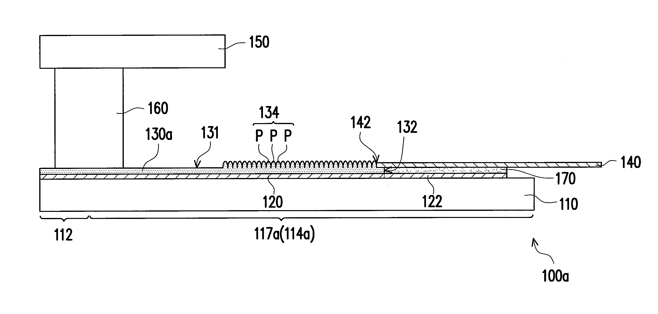
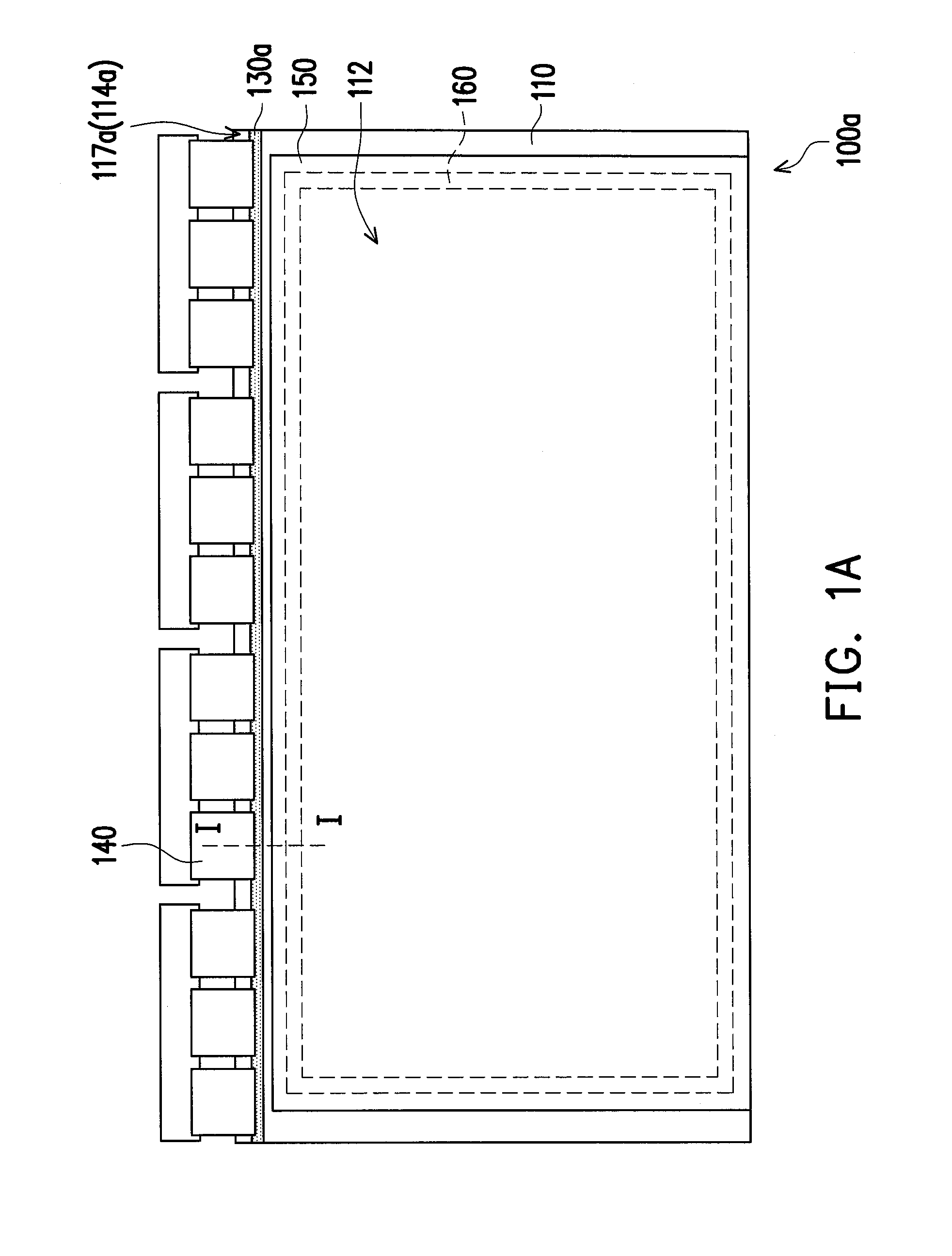
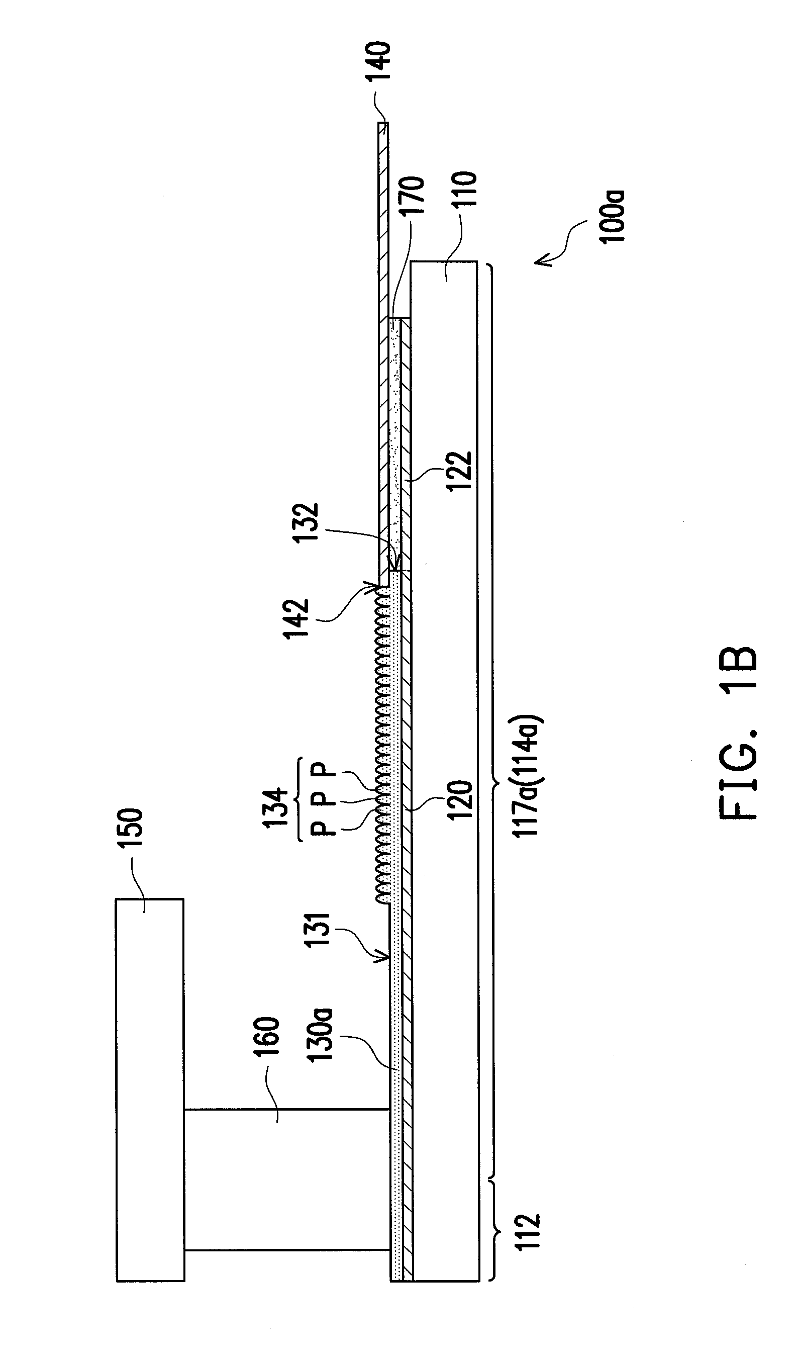
[0024]FIG. 1A is a top view schematically illustrating a display device according to an embodiment of the present invention. FIG. 1B schematically illustrates a cross-sectional view of FIG. 1A along a profile line I-I. Referring to FIG. 1A and FIG. 1B together, in the present embodiment, a display device 100a includes a first substrate 110, at least one trace 120, a hydrophobic protective layer 130a, a flexible printed circuit board 140, a second substrate 150 and a sealant 160. In detail, the first substrate 110 has a display region 112 and a peripheral region 114a located around the display region 112. The peripheral region 114a has an outer lead bonding portion 117a connected to the display region 112. The trace 120 is disposed on the first substrate 110 and extends from the display region 112 into the outer lead bonding portion 117a of the peripheral region 114a. The hydrophobic protective layer 130a is disposed on the first substrate 110 and extends from the display region 112 ...


PUM


Abstract

A display device includes a first substrate, at least one trace, a hydrophobic protective layer, a flexible printed circuit board (FPCB), a second substrate and a sealant. The first substrate has a display region and a peripheral region having an outer lead bonding (OLB) portion. The trace and the hydrophobic protective layer are disposed on the first substrate and extend from the display region to the OLB portion. The hydrophobic protective layer covers the trace and has at least one opening exposing a portion of the trace to define at least one lead and a surface microstructure. The lead and the surface microstructure are located in the OLB portion, and the surface microstructure is located on a surface of the hydrophobic protective layer away from the trace. One end of the FPCB leans against the surface microstructure and the FPCB is electrically connected to the lead.

Description

CROSS-REFERENCE TO RELATED APPLICATION[0001]This application claims the priority benefit of Taiwan application serial no. 103122676, filed on Jul. 1, 2014. The entirety of the above-mentioned patent application is hereby incorporated by reference herein and made a part of this specification.BACKGROUND OF THE INVENTION[0002]1. Field of the Invention[0003]The present invention generally relates to a display device, and more particularly, to a display device having favorable structure structural reliability.[0004]2. Description of Related Art[0005]In general, conventional display device is usually configured with a protective glue (such as Tiffy glue) in an out lead bonding region of a peripheral region for protecting leads of peripheral circuit and strengthening the protection of signal traces. However, the protective glue has a rework characteristic, and thereby an adhesion thereof is relatively weak. In addition, a cleaning liquid for cleaning the display device is apt to infiltrate...

Claims


Application Information

Patent Timeline
IPC IPC(8): H05K3/28H05K1/03
CPCH05K3/28H05K2203/1173H05K2201/10128H05K1/0393H05K3/361H05K2201/10977G02F1/1345G02F2201/50G02F2202/36C09K2323/05B32B2457/202B32B2457/20B32B2457/204B32B2457/208B32B2457/206
Inventor LAI, CHING-KUNCHI, CHUN-CHICHENG, KAI-TZU
Owner AU OPTRONICS CORP
Learn More