Cone shaped crusher
a cone crusher and cone shape technology, applied in the field of cone crushers, can solve the problems of destroying the surface of the crushing head and main shaft by sliding friction, rapid leakage of hydraulic fluid, and the liner of lubricious material is also subject to gradual wear, so as to reduce the influx of foreign matter, reduce the risk of surface damage, and the probability of leakage low
- Summary
- Abstract
- Description
- Claims
- Application Information
AI Technical Summary
Benefits of technology
Problems solved by technology
Method used
Image
Examples
first embodiment
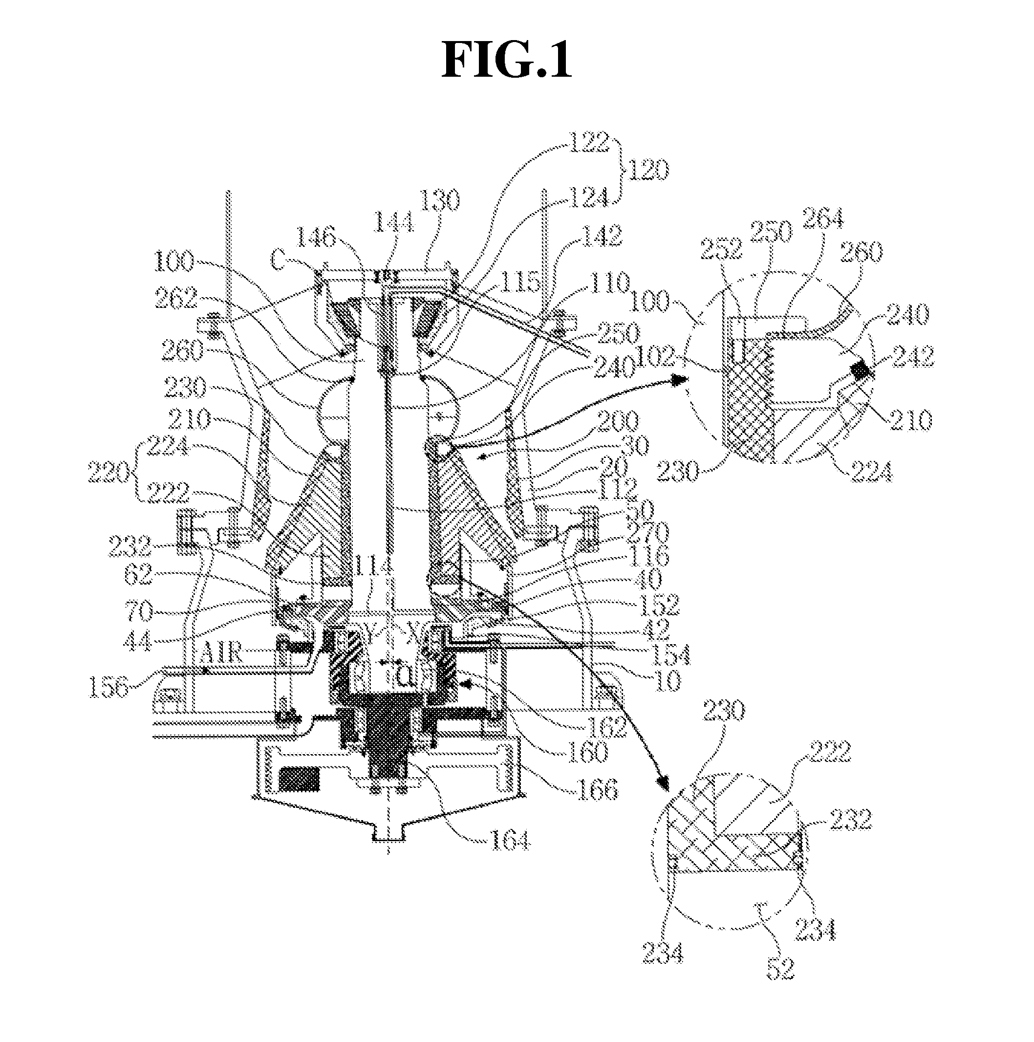
[0053]FIG. 1 is a sectional view illustrating a cone-shaped crusher according to a
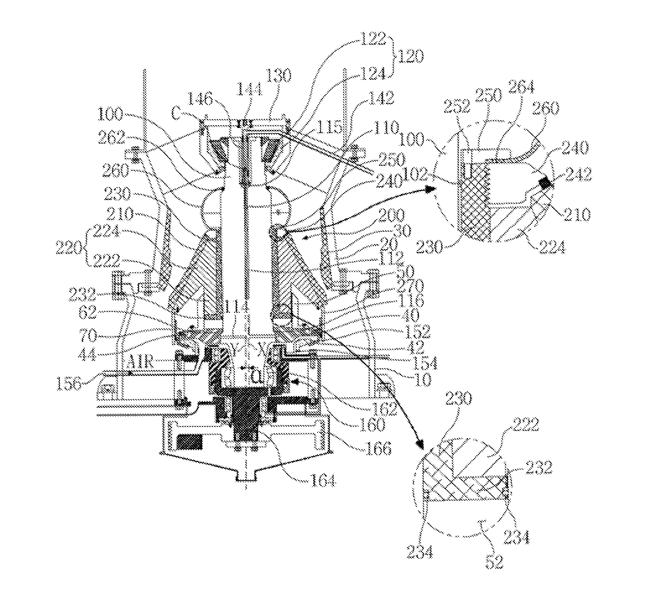
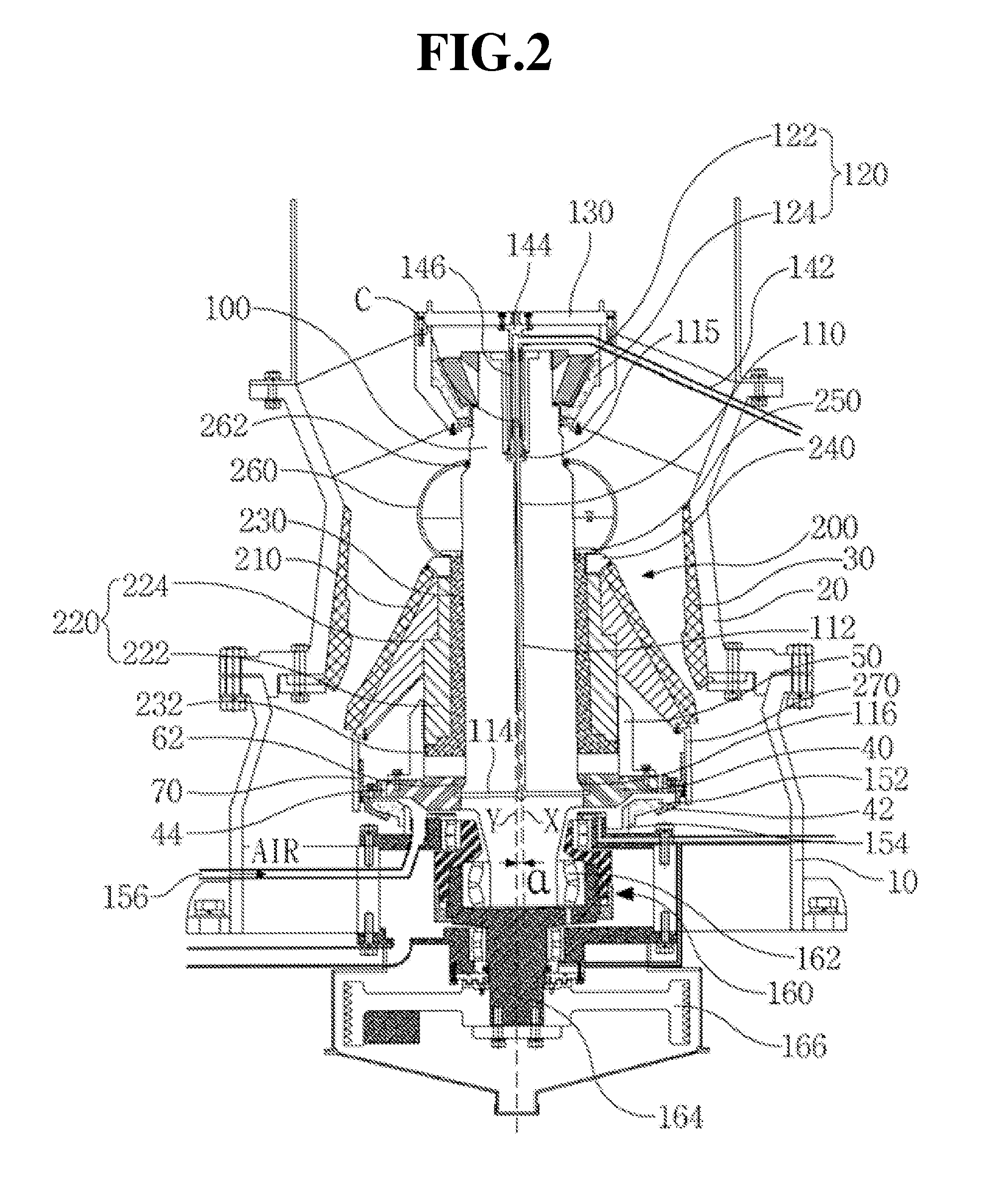
[0054]Referring to FIG. 1, the conical crusher according to the first embodiment includes a frame having a cavity formed therein, a main shaft 100 disposed in the cavity of the frame eccentrically from the center axis of the frame to perform a gyratory movement, a mantle core assembly 200 which is coupled to the main shaft 100 for maintaining a common gyratory movement and is movable along longitudinal direction of the main shaft 100, and a concave 30 mounted on the inner circumferential surface of the frame that faces the mantle core assembly 200. The conical crusher further includes a crushing gap control support 40 which is located below the mantle core assembly 200 and is fixed to the main shaft 100, an eccentric driver 160 for driving the main shaft 100 to be eccentrically offset from a center axis (Y) of the frame, a main shaft driving means for rotating the eccentric driver 160 to generate the g...
third embodiment
[0116]FIG. 3 is a sectional view showing a conical crusher according to the present disclosure.
[0117]In the following description of the third embodiment referring to FIG. 3. To avoid repeated description, distinctive features from the first embodiment will be rather discussed. Compared to the first embodiment, the third embodiment has a different eccentric driver 170 and a different driving means for the main shaft and replaces the suspension bearing 120 by a conventional bearing 126.
[0118]In the third embodiment, the eccentric driver 170 is provided with an eccentric sleeve 175 equipped with journaled bearings 171 and 172 and a bevel gear 176 formed on the external periphery surfaces of the eccentric sleeve 175. Accepting the lower end of the main shaft 100 in its eccentric center bearing, the eccentric sleeve 175 itself rotates in a coaxial arrangement with central axis Y.
[0119]Inserting the lower end of the main shaft 100 into the eccentric sleeve 175 will tilt central axis X of...
PUM
 Abstract
Description
Claims
Application Information
 - R&D
- Intellectual Property
- Life Sciences
- Materials
- Tech Scout
- Unparalleled Data Quality
- Higher Quality Content
- 60% Fewer Hallucinations
Browse by: Latest US Patents, China's latest patents, Technical Efficacy Thesaurus, Application Domain, Technology Topic, Popular Technical Reports.
© 2025 PatSnap. All rights reserved.Legal|Privacy policy|Modern Slavery Act Transparency Statement|Sitemap|About US| Contact US: help@patsnap.com


