Aircraft fuel system

a fuel system and aircraft technology, applied in aircraft power plants, aircraft components, transportation and packaging, etc., to achieve the effect of reducing the oxygen content of the ullag

Inactive Publication Date: 2016-01-14
AIRBUS OPERATIONS LTD
View PDF2 Cites 8 Cited by
  • Summary
  • Abstract
  • Description
  • Claims
  • Application Information

AI Technical Summary

Benefits of technology

[0025]Preferably, the aircraft fuel system further comprises an inerting system for reducing the oxygen content of the ullage.
[0026]More preferably, the inerting system is connected to the ullage storage facility so as to act upon the ullage in the ullage storage facility to reduce its oxygen content.

Problems solved by technology

This could be a large cost saving, as water-related maintenance of a fuel system could be as much as half of the total fuel system maintenance cost.

Method used


Image

  • Aircraft fuel system
  • Aircraft fuel system
  • Aircraft fuel system

Examples


Embodiment Construction

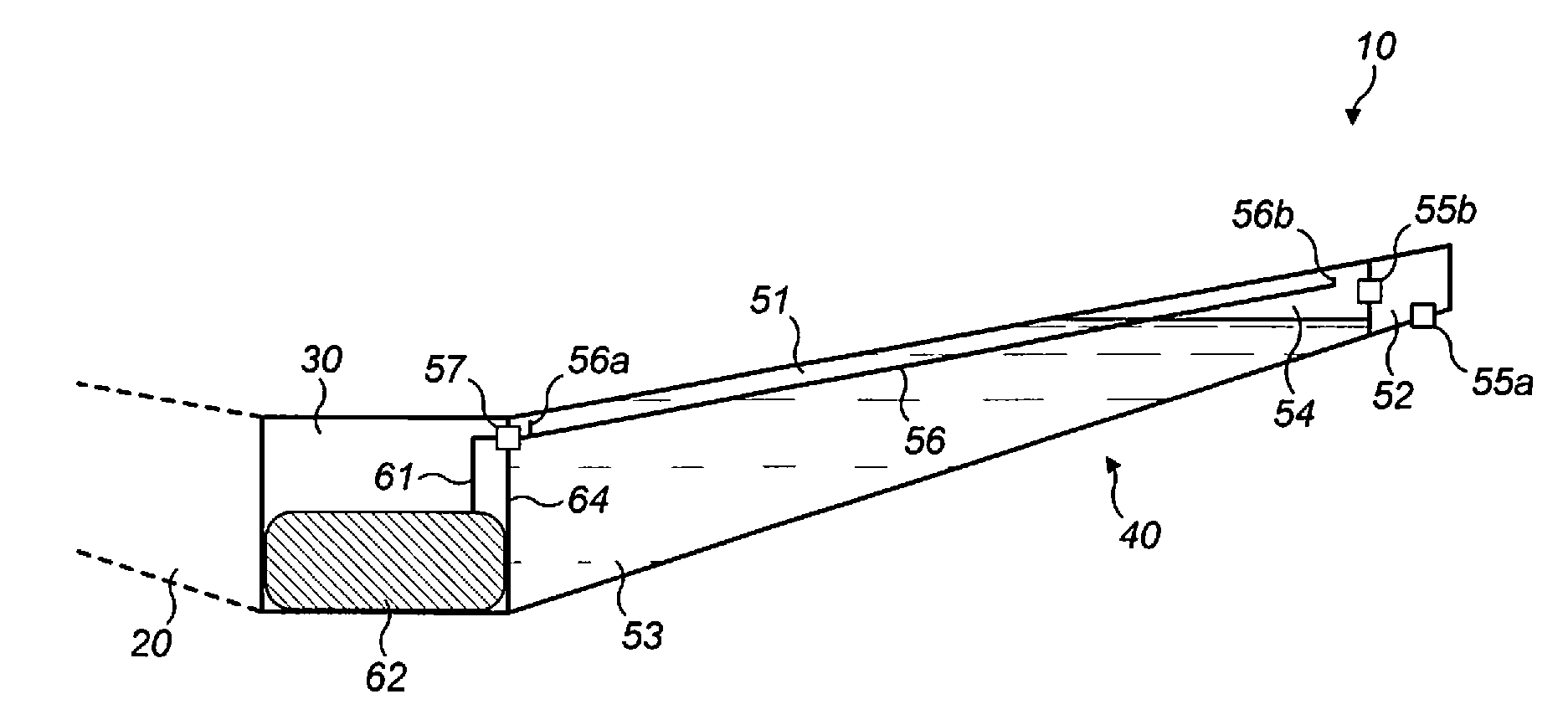
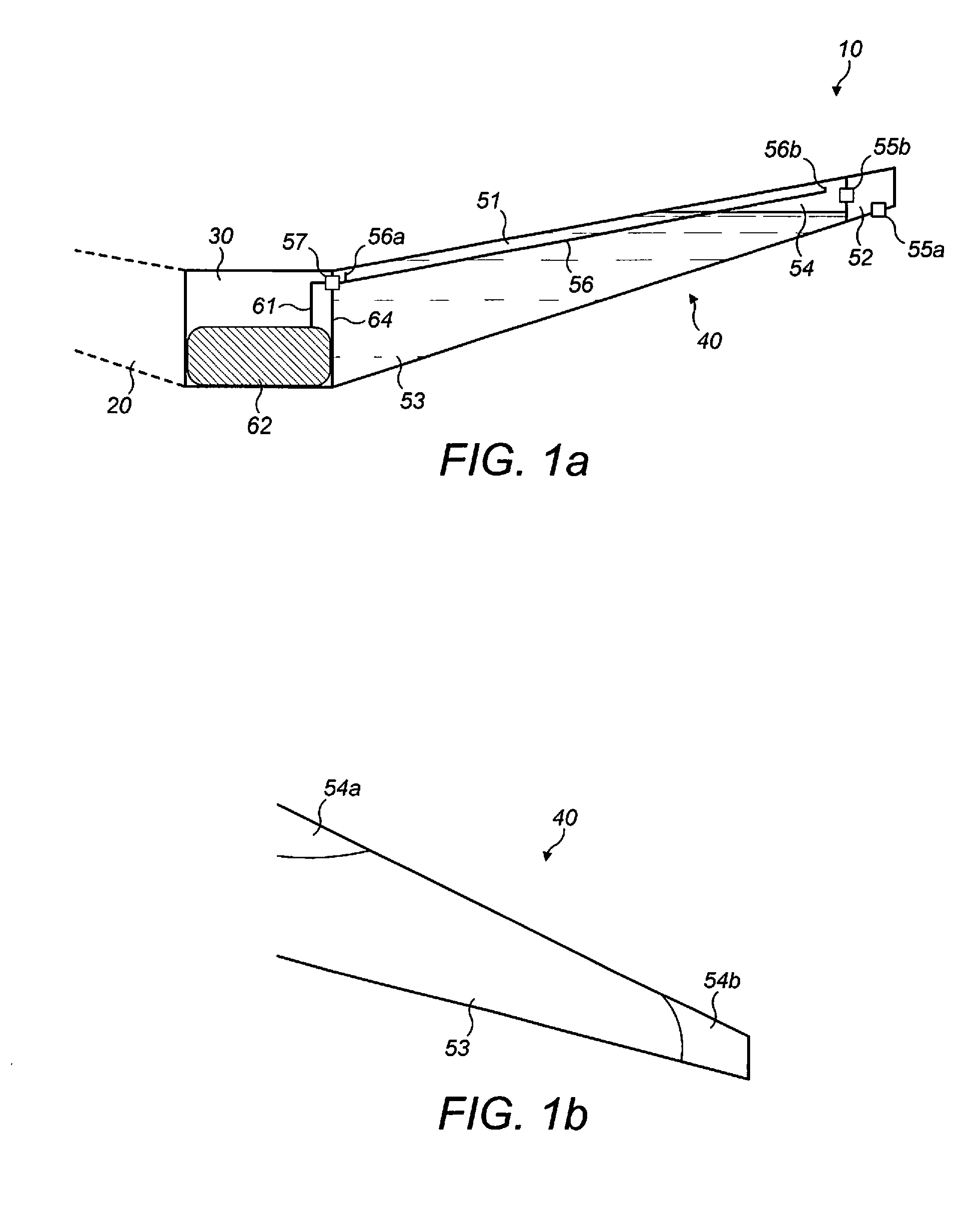
[0045]FIG. 1a shows a schematic rear view of part of an aircraft 10 according to a first embodiment of the invention. The aircraft 10 comprises a port wing 20, a centre wing box 30, and a starboard wing 40. The tank arrangement of the starboard wing 40 will now be described in more detail.

[0046]The starboard wing 40 comprises a fuel tank 51, taking up most of the space in the wing, and a surge / vent tank 52, at an outboard tip of the wing 40. The fuel tank 51 holds fuel 53 and also ullage 54 (the gas above the fuel in the tank). The ullage 54 contains fuel vapour.

[0047]A climb-dive valve 55 is located adjacent the surge tank. The Figure shows two possible locations for the valve; a first location at the very tip of the wing, outboard of the surge / vent tank 55a at a NACA duct outlet (not shown) and a second location inboard of the surge / vent tank 55b in the vent system ducting (not shown).

[0048]In either position, the climb dive valve 55 is a two-way valve that partially pressurises t...


PUM


Abstract

The invention provides an aircraft fuel system comprising a fuel storage facility for storing fuel and ullage, a separate ullage storage facility for storing ullage, and a transfer arrangement for transferring ullage between the fuel storage facility and the ullage storage facility, wherein the transfer arrangement is capable of controlling the transfer of ullage based on a pressure input to the transfer arrangement. The invention also provides an aircraft with such a fuel system and a method of operating an aircraft.

Description

BACKGROUND OF THE INVENTION[0001]The present invention relates to an aircraft fuel system comprising a fuel storage facility for storing fuel and ullage. The present invention also relates to an aircraft with such a fuel system and a method of operating an aircraft.[0002]Aircraft fuel is stored in one or more aircraft tanks. Air that contains fuel vapour, such as the air above the fuel in the fuel tanks, is known as ullage. When an aircraft is refuelled, the pressure in the fuel tanks is high and, in order to prevent a large difference in pressure between the tank and the atmosphere (to prevent damage to the wing), ullage is expelled into the atmosphere. Similarly, upon aircraft ascent, ullage is expelled to the atmosphere. This causes fuel vapour to be emitted, which may be harmful to the environment.[0003]Upon aircraft descent, especially after fuel has been depleted, in order for the pressure in the fuel tanks to be increased to reduce the pressure difference between the fuel tan...

Claims


Application Information

Patent Timeline
Patent Type & Authority Applications(United States)
IPC IPC(8): B64D37/10B64D37/32
CPCB64D37/32B64D37/10B64D37/02B64D37/04B64D37/14B64D37/24
Inventor BURNELL, STEPHENLEIGH, TIM
Owner AIRBUS OPERATIONS LTD
Why Eureka
Try Eureka