EGR mixer for high-boost engine systems

a mixer and high-boom technology, applied in the field of exhaust gas recirculation in motor vehicles, can solve the problems of accelerating material aging in the engine and associated exhaust system, and reducing combustion and exhaust temperatures. , to achieve the effect of reducing oxygen content, increasing combustion and exhaust temperatures, and increasing nitrogen-oxide (nox) emissions

Active Publication Date: 2011-11-15
FORD GLOBAL TECH LLC
View PDF37 Cites 36 Cited by
  • Summary
  • Abstract
  • Description
  • Claims
  • Application Information

AI Technical Summary

Benefits of technology

[0002]A boosted engine may exhibit higher combustion and exhaust temperatures than a naturally aspirated engine of equivalent output power. Such higher temperatures may increase nitrogen-oxide (NOX) emissions and cause accelerated materials aging in the engine and associated exhaust system. Exhaust-gas recirculation (EGR) is one approach for combating these effects. EGR strategies reduce the oxygen content of the intake air charge by diluting it with exhaust. When the diluted air-exhaust mixture is used in place of ordinary air to support combustion in the engine, lower combustion and exhaust temperatures result. EGR also improves fuel economy in gasoline engines by reducing throttling losses and heat rejection.
[0003]In a boosted engine system equipped with a turbocharger compressor and a turbine, exhaust may be recirculated through a high pressure (HP) EGR loop or a low-pressure (LP) EGR loop. In the HP EGR loop, the exhaust is drawn from upstream of the turbine and is mixed with intake air downstream of the compressor. In the LP EGR loop, the exhaust is drawn from downstream of the turbine and is mixed with intake air upstream of the compressor. HP and LP EGR strategies achieve optimum efficacy in different regions of the engine load-speed map. For example, on boosted gasoline engines running stoichiometric air-to-fuel ratios, HP EGR is desirable at low loads, where intake vacuum provides ample flow potential; LP EGR is desirable at higher loads, where the LP EGR loop provides the greater flow potential. Various other trade-offs between the two strategies exist as well, both for gasoline and diesel engines. Such complementarity has motivated engine designers to consider EGR systems having both an HP EGR loop and an LP EGR loop.
[0004]To enable appropriate control of EGR dilution levels and protect combustion stability, the recirculated exhaust is homogenized with the intake air charge, for example via an EGR mixer. However, some EGR mixers suffer a trade-off between effective homogenization on the one hand and excessive air-flow restriction on the other. In other words, the flow elements that provide effective homogenization also cause drag in the intake air flow, which reduces overall efficiency. Conversely, EGR mixers that present minimal drag may not provide adequate homogenization at every mixing point and operating condition. The EGR mixer described in U.S. Pat. No. 7,568,340, for example, may present relatively little intake-air flow restriction. However, this mixer is configured for use in an LP EGR loop, where the long flow path and compressor action provide further homogenization, thereby reducing the performance demand on the mixer.
[0005]The inventors herein have recognized these issues and have devised a series of approaches to address them. Therefore, one embodiment of this disclosure provides an EGR mixer comprising an upstream conduit section having a contracting flow area in a direction of air flow through the mixer, a downstream conduit section having an expanding flow area in the direction of air flow through the mixer, a slot formed in the downstream conduit section for admitting exhaust to the air flow, and an abrupt flow-expanding ridge disposed between the upstream and downstream conduit sections. With an EGR mixer configured in this manner, recirculated exhaust may be effectively homogenized into an intake air flow with reduced drag. For example, the upstream and downstream conduit section may enable increase EGR flow to be drawn into the airflow, where the abrupt ridge operates to increase mixing of the EGR in the airflow.

Problems solved by technology

Such higher temperatures may increase nitrogen-oxide (NOX) emissions and cause accelerated materials aging in the engine and associated exhaust system.
When the diluted air-exhaust mixture is used in place of ordinary air to support combustion in the engine, lower combustion and exhaust temperatures result.
However, some EGR mixers suffer a trade-off between effective homogenization on the one hand and excessive air-flow restriction on the other.
In other words, the flow elements that provide effective homogenization also cause drag in the intake air flow, which reduces overall efficiency.
Conversely, EGR mixers that present minimal drag may not provide adequate homogenization at every mixing point and operating condition.
However, this mixer is configured for use in an LP EGR loop, where the long flow path and compressor action provide further homogenization, thereby reducing the performance demand on the mixer.

Method used


Image

  • EGR mixer for high-boost engine systems
  • EGR mixer for high-boost engine systems
  • EGR mixer for high-boost engine systems

Examples


Embodiment Construction

[0009]The subject matter of this disclosure is now described by example and with reference to the illustrated embodiments listed above. Components, process steps, and other elements that may be substantially the same in one or more embodiments are identified coordinately and are described with minimal repetition. It will be noted, however, that elements identified coordinately may also differ to some degree.

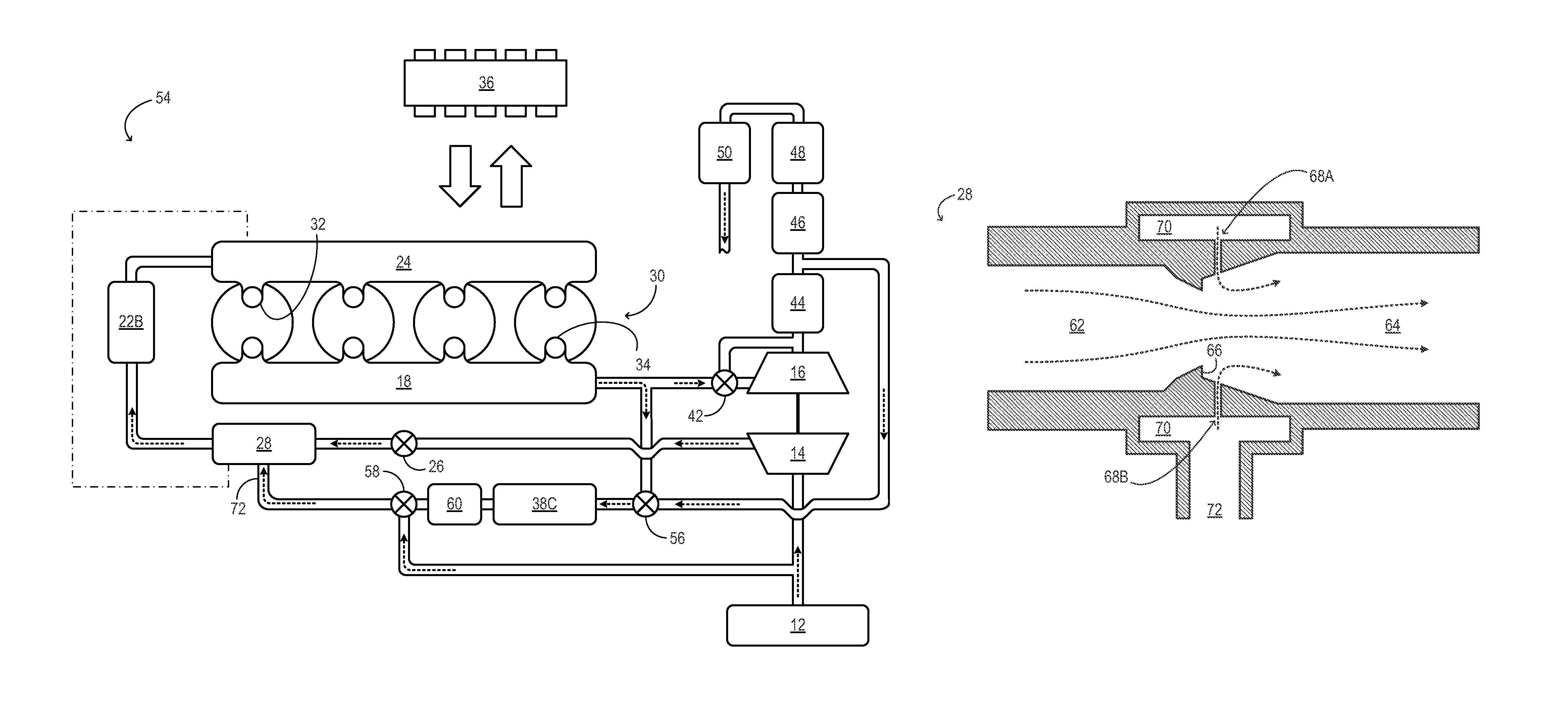
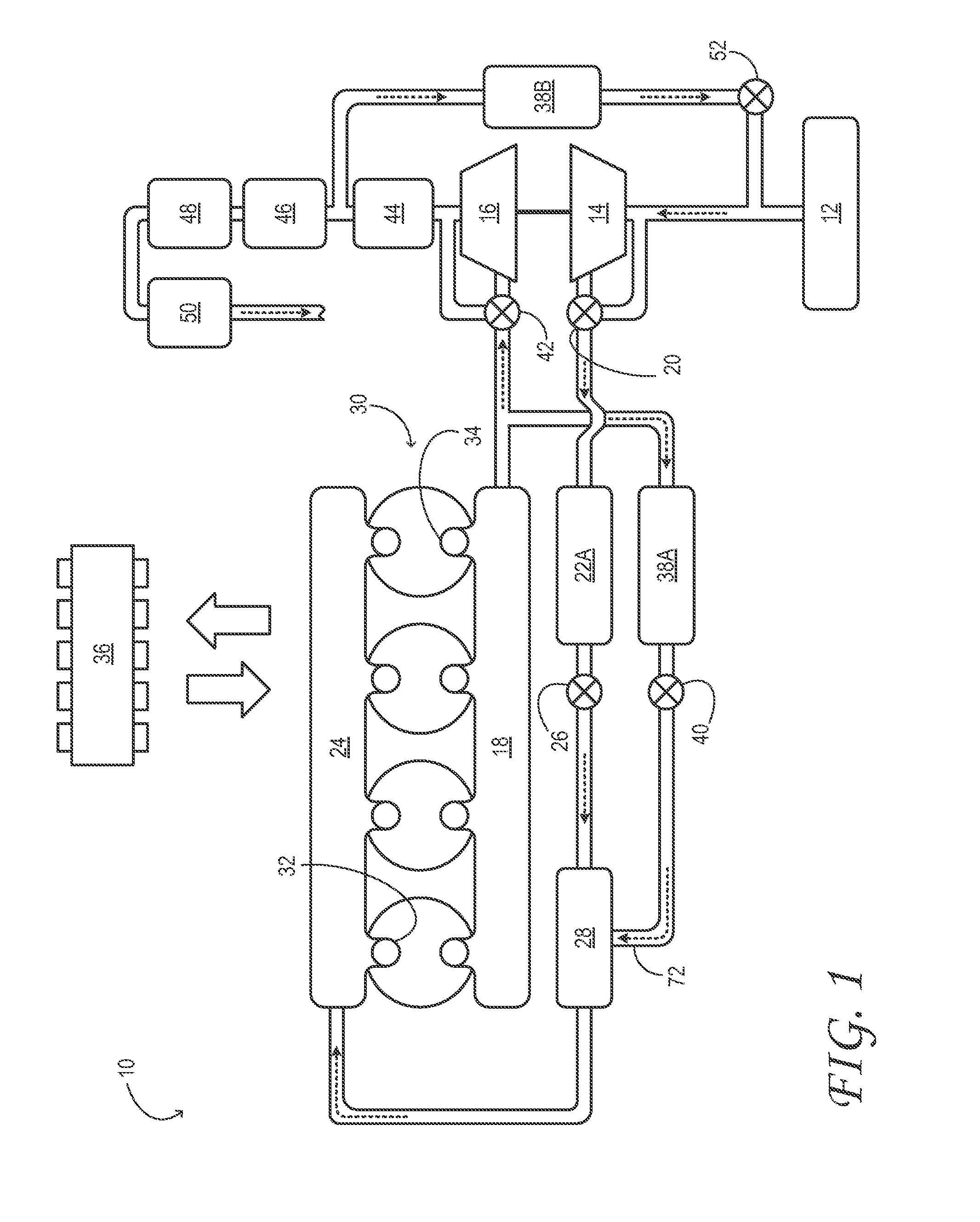
[0010]FIG. 1 schematically shows aspects of an example engine system 10 in one embodiment. In engine system 10, air cleaner 12 is coupled to the inlet of compressor 14. The air cleaner inducts fresh air from the ambient and supplies filtered, fresh air to the compressor. The compressor may be any suitable intake-air compressor—a motor or drive-shaft driven supercharger compressor, for example. In the embodiment illustrated in FIG. 1, however, the compressor is a turbocharger compressor mechanically coupled to turbine 16, the turbine driven by expanding engine exhaust from exhaust...


PUM


Abstract

An EGR mixer comprises an upstream conduit section having a contracting flow area in a direction of air flow through the mixer, a downstream conduit section having an expanding flow area in the direction of air flow through the mixer, a slot formed in the downstream conduit section for admitting exhaust to the air flow, and an abrupt flow-expanding ridge disposed between the upstream and downstream conduit sections. With the EGR mixer configured in this manner, recirculated exhaust may be effectively homogenized into an intake air flow with reduced drag.

Description

TECHNICAL FIELD[0001]This application relates to the field of motor-vehicle engineering, and more particularly, to exhaust-gas recirculation in motor-vehicle engine systems.BACKGROUND AND SUMMARY[0002]A boosted engine may exhibit higher combustion and exhaust temperatures than a naturally aspirated engine of equivalent output power. Such higher temperatures may increase nitrogen-oxide (NOX) emissions and cause accelerated materials aging in the engine and associated exhaust system. Exhaust-gas recirculation (EGR) is one approach for combating these effects. EGR strategies reduce the oxygen content of the intake air charge by diluting it with exhaust. When the diluted air-exhaust mixture is used in place of ordinary air to support combustion in the engine, lower combustion and exhaust temperatures result. EGR also improves fuel economy in gasoline engines by reducing throttling losses and heat rejection.[0003]In a boosted engine system equipped with a turbocharger compressor and a tu...

Claims


Application Information

Patent Timeline
Patent Type & Authority Patents(United States)
IPC IPC(8): F02B33/44F02M25/07F02M35/10
CPCF02B33/44F02B37/127F02B37/18F02M25/0707F01N13/009F02M25/0722F02M25/0709Y02T10/121Y02T10/144F02M26/05F02M26/06F02M26/19F02B37/162Y02T10/12
Inventor VAUGHT, AUGUST THOMASSHAIKH, FURQAN ZAFARMARSHALL, LAWRENCEWOODSIDE, WAYNE PAULMACERONI, KAREN ELIZABETHSTYLES, DANIEL JOSEPH
Owner FORD GLOBAL TECH LLC
Why Eureka
Try Eureka