Magnetic switch

a technology of magnetic switch and spring, which is applied in the direction of magnets, contact mechanisms, magnets, etc., can solve the problem of not being able to enhance the compressive force of the spring in a limited space, and achieve the effect of enhancing short-circuit performan

Active Publication Date: 2016-01-14
LSIS CO LTD
View PDF30 Cites 4 Cited by
  • Summary
  • Abstract
  • Description
  • Claims
  • Application Information

AI Technical Summary

Benefits of technology

[0015]Therefore, an aspect of the detailed description is to provide a magnetic swi

Problems solved by technology

In the related art, maximum compressive force of a spring is proportional to a compression distance of the sp

Method used


Image

  • Magnetic switch
  • Magnetic switch
  • Magnetic switch

Examples


Embodiment Construction

[0032]Description will now be given in detail of the exemplary embodiments, with reference to the accompanying drawings. For the sake of brief description with reference to the drawings, the same or equivalent components will be provided with the same reference numbers, and description thereof will not be repeated.

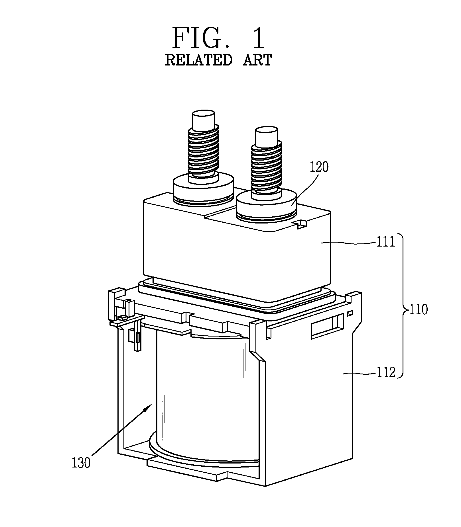
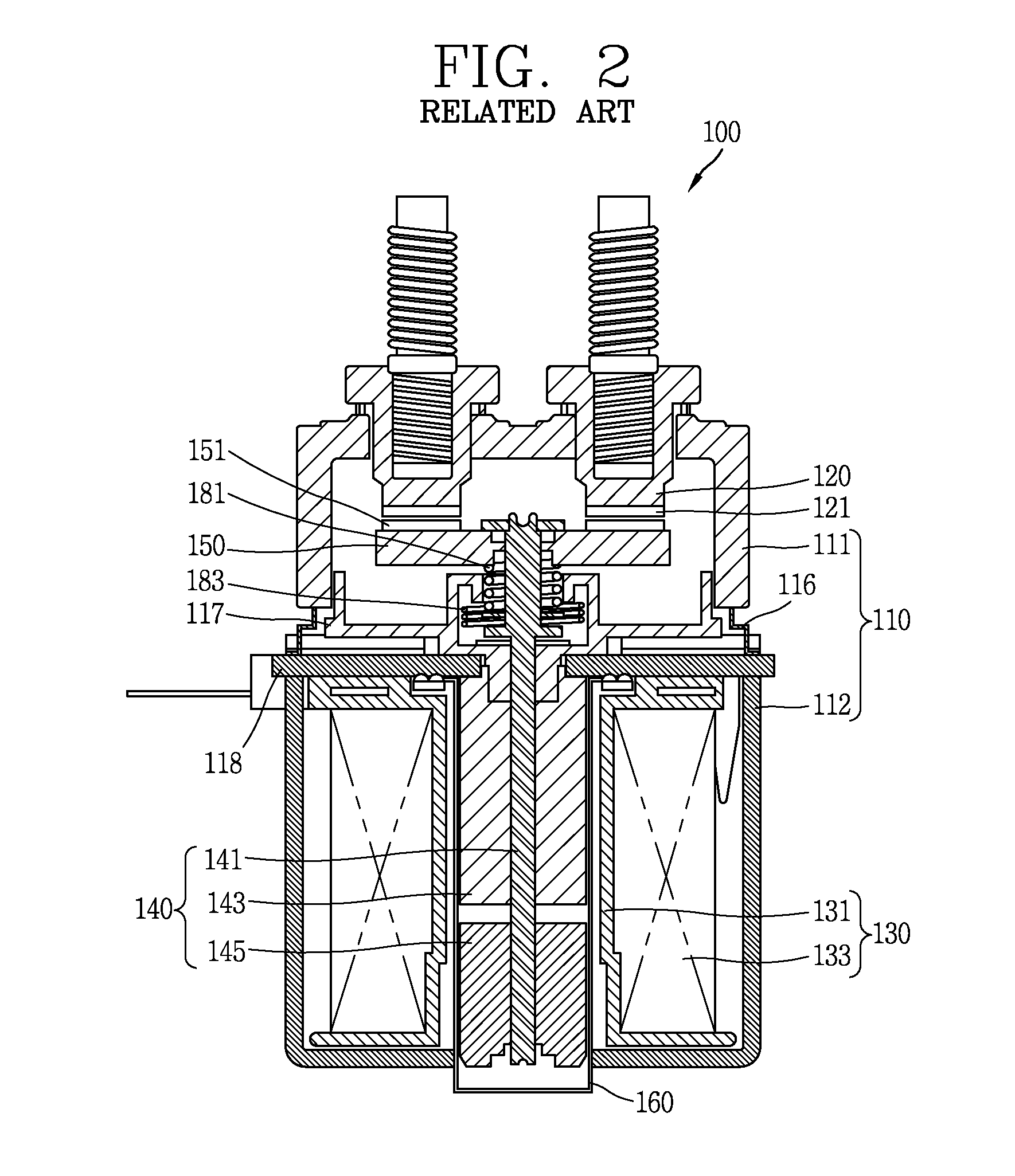
[0033]Hereinafter, a magnetic switch according to an embodiment of the present disclosure will be described in detail with reference to the accompanying drawings. Parts of the magnetic switch similar to those of the related art will be briefly described within a range required for describing the characteristics of the present disclosure.

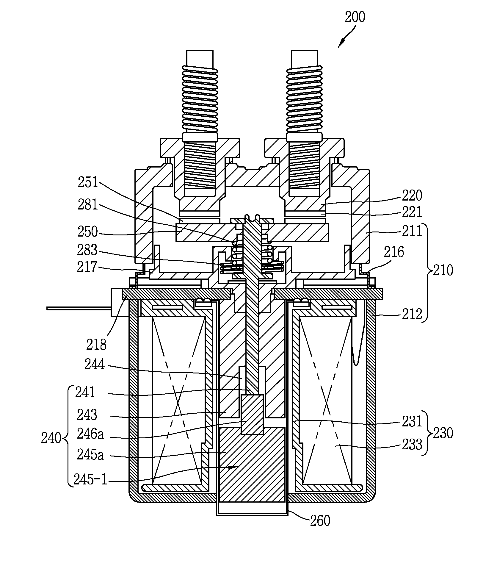
[0034]FIG. 3 is a cross-sectional view of a magnetic switch 200 according to an embodiment of the present disclosure. As illustrated in FIG. 3, a movable shaft 241 is positioned to be movable within a housing 210, and a movable contact arm 250 is coupled to an upper portion of the movable shaft 241. Accordingly, when movable cores 245-1 and...


PUM


Abstract

A magnetic switch includes: a housing; a cylinder coupled to an inner side of the housing; a stationary contact arm coupled to the housing; a movable contact arm positioned to be movable within the housing and brought into contact with the stationary contact arm or separated therefrom; a coil assembly installed within the housing and configured to form a magnetic field when a current is applied thereto; a movable shaft coupled to the movable contact arm in an upper portion thereof; a fixed core inserted into the cylinder and surrounding the movable shaft; and movable cores fixed to the movable shaft and configured to press the movable shaft by a magnetic field formed by the coil assembly to move the movable shaft.

Description

CROSS-REFERENCE TO RELATED APPLICATION[0001]Pursuant to 35 U.S.C. §119(a), this application claims the benefit of earlier filing date and right of priority to Korean Application No. 10-2014-0087645, filed on Jul. 11, 2014, the contents of which is incorporated by reference herein in its entirety.BACKGROUND OF THE INVENTION[0002]1. Field of the Invention[0003]The present disclosure relates to a magnetic switch.[0004]2. Background of the Invention[0005]A magnet switch is a device used for switching (opening or closing) power of an electric line, and is extensively utilized for industrial, household, and vehicle purposes. In particular, a magnetic switch for a vehicle is used to supply and cut off DC power provided from a storage battery of a vehicle such as a hybrid vehicle, a fuel cell vehicle, or a golf cart.[0006]Such a magnetic switch is closed and a current flows when a stationary contact arm and a movable contact arm are brought into contact with each other, and in particular, i...

Claims


Application Information

Patent Timeline
IPC IPC(8): H01H50/56H01F7/02H01H50/04H01H50/18H01H50/44H01H50/64
CPCH01H50/56H01H50/04H01H50/44H01H2036/0086H01H50/18H01H50/645H01F7/0278H01H50/16H01H50/54H01H50/20H01H51/065
Inventor SON, SOL, SAN
Owner LSIS CO LTD
Why Eureka
Try Eureka