Electrical receptacle connector

a technology of electrical receptacles and connectors, which is applied in the direction of coupling devices, two-part coupling devices, electrical apparatus, etc., can solve the problems of insufficient transmission rate of usb 2.0, inability to reduce the additional manufacturing cost and manufacturing time of usb 2.0 connectors, and insufficient usb 2.0 transmission rate. , to achieve the effect of effective noise grounding and conduction, reducing the manufacturing cost of electrical receptacle connectors, and simplifying the manufacturing process

Active Publication Date: 2016-01-14
ADVANCED CONNECTEK INC
View PDF6 Cites 17 Cited by
  • Summary
  • Abstract
  • Description
  • Claims
  • Application Information

AI Technical Summary

Benefits of technology

[0008]In conclusion, when the contacts between the tail portions of the lower-row receptacle terminals (namely, the contacts of the grounding sheet), are omitted, the electrical receptacle connector can transmit USB 2.0 signals without changing or rearranging the configuration of the lower-row receptacle terminals. Therefore, when the electrical receptacle connector is provided for transmitting USB 2.0 signals, manufacturing steps for the grounding sheet and the contacts of the grounding sheet can be omitted so as to simplify the manufacturing process of the electrical receptacle connector and redu

Problems solved by technology

The transmission rate of USB 2.0 is insufficient.
However, due to the rigid architecture of the connector, it is hard to make connectors for transmitting USB 2.0 signals by simply removing the high-speed ter

Method used


Image

  • Electrical receptacle connector
  • Electrical receptacle connector
  • Electrical receptacle connector

Examples


first embodiment

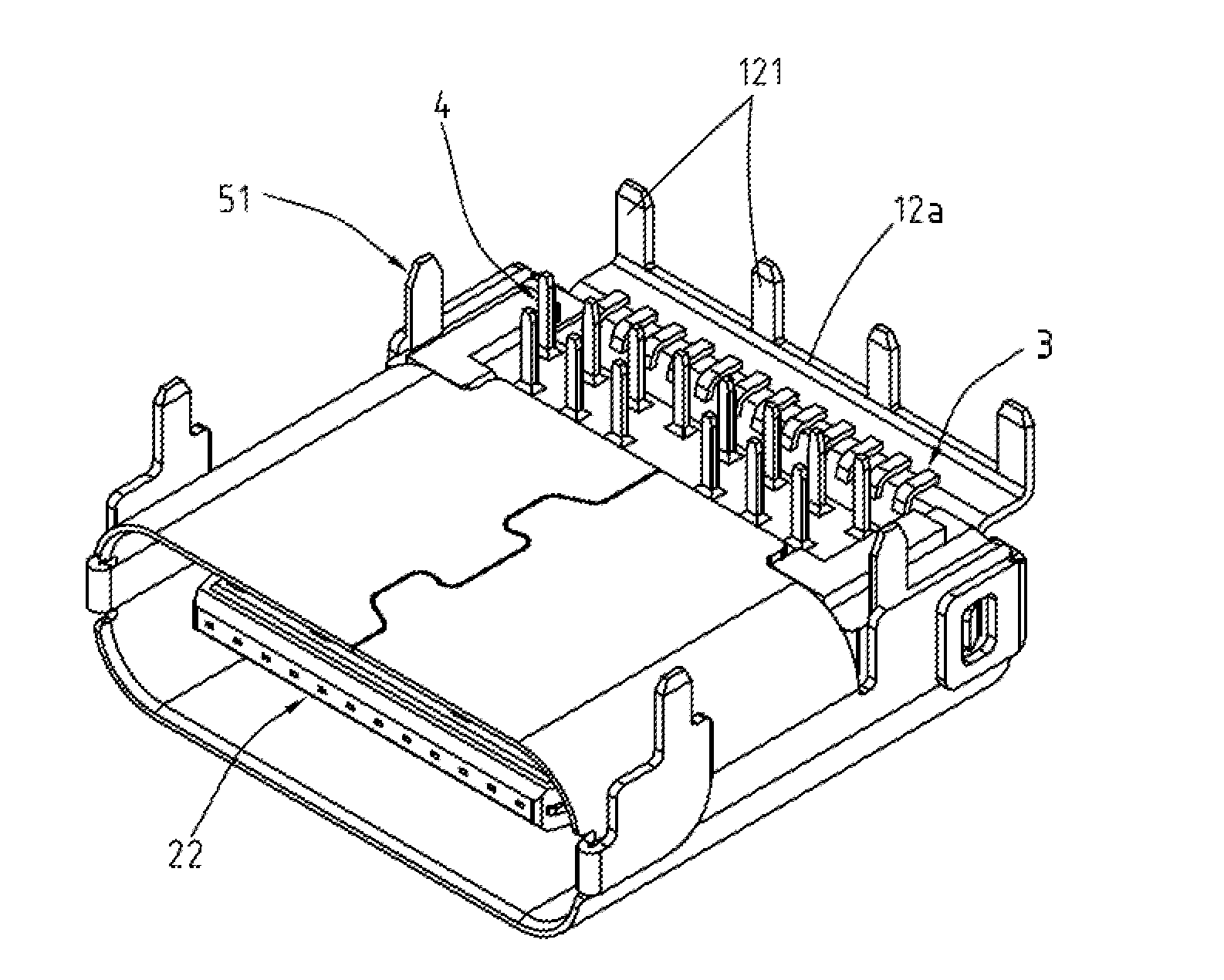
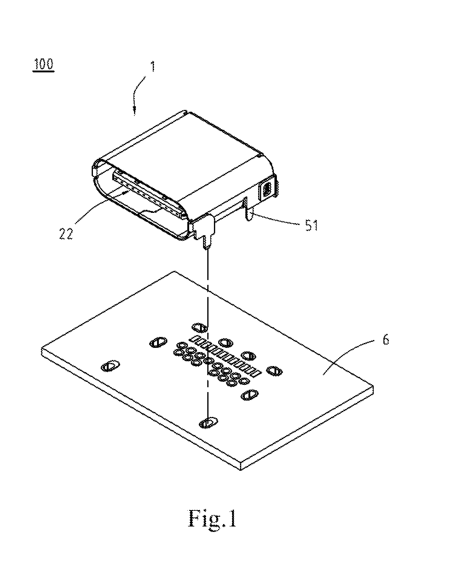
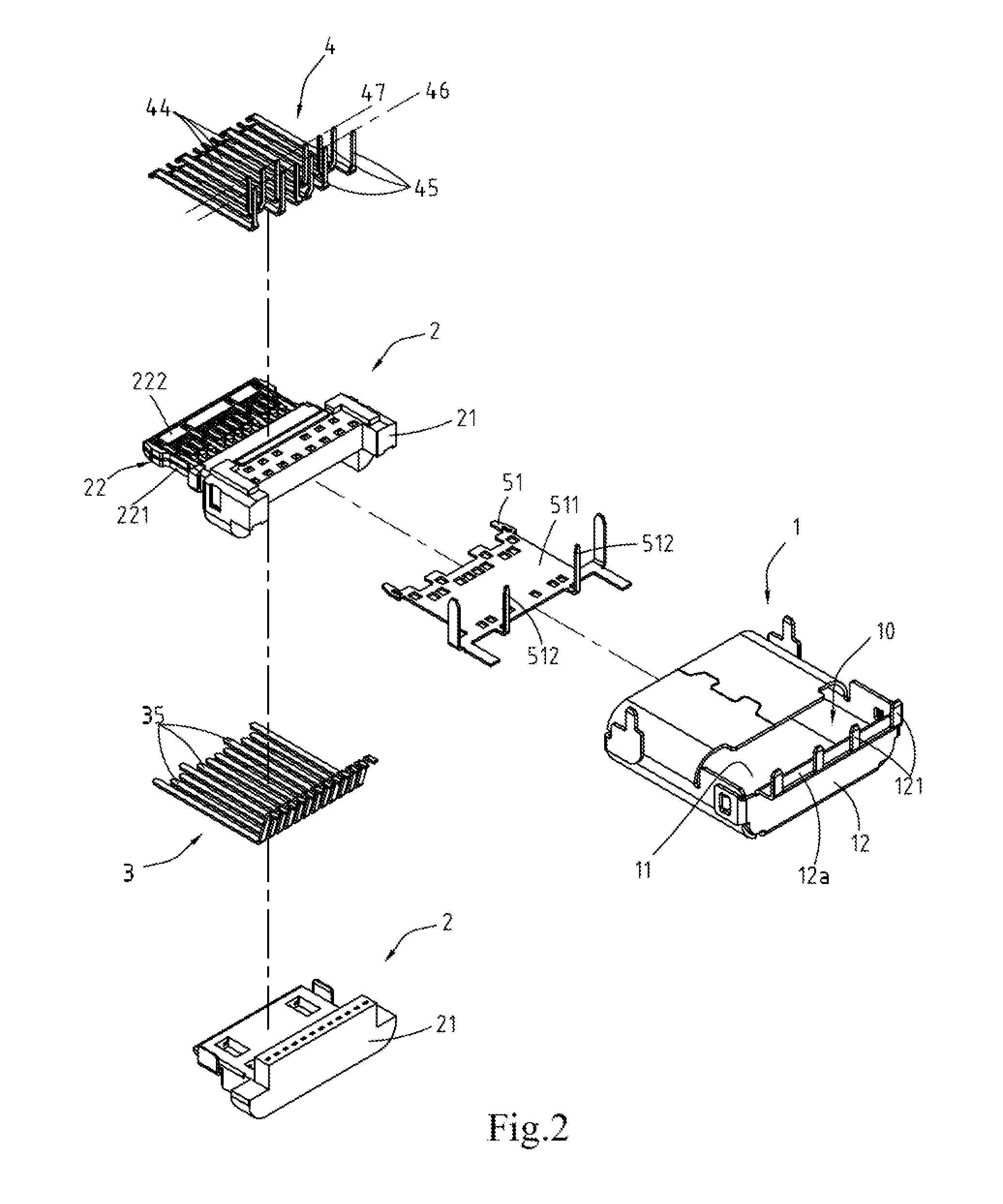
[0027]FIG. 6 is a back perspective view of the electrical receptacle connector 100 of the Please refer to FIG. 2 and FIG. 6, in which the metallic shell 1 is a hollowed shell and defines a receptacle cavity 10 therein. The insulated housing 2 is received in the metallic shell 1. In this embodiment, the metallic shell 1 comprises a top cover plate 11, a rear cover plate 12, and a plurality of pins 121. The top cover plate 11 is at a top plane of the insulated housing 2, and the rear cover plate 12 is extended from a back side of the top cover plate 11 and extended downward to the back of the insulated housing 2, as shown in FIG. 1. That is, the rear cover plate 12 covers a back side of the receptacle cavity 10. Additionally, the rear cover plate 12 comprises a bottom plane 12a, and the pins 121 are through-hole legs and extended downward from the bottom plane 12a. That is, the pins are extended from the metallic shell to form vertical legs, named through-hole legs which can be solde...

second embodiment

[0044]FIG. 11B is a bottom view of the electrical receptacle connector 100 assembled with the circuit board 6, of the second embodiment, for another implementation aspect. Please refer to FIG. 10 and FIG. 11B, the second row 47 of the tail portions 442 are disposed between the row of the tail portions 352 and the first row 46 of the tail portions 442. That is, the positions of the first row 46 and the second row 47 of the tail portions 442 are exchanged with each other to be the pin assignment shown in FIG. 11B. It is understood that, in the aforementioned two configurations, each of the lower-row receptacle terminals 4 transmits a constant signal no matter where the terminal is located at. Here, the grounding sheet 51 of the electrical receptacle connector 100 can be omitted, and the first row 46 of the tail portions 442 comprises the first pin 461, the second pin 462, the first set of pins 463, and the first reserved regions 464, as described above. The second row 47 of the tail p...


PUM


Abstract

An electrical receptacle connector includes a metallic shell, an insulated housing, a plurality of upper-row receptacle terminals, and a plurality of lower-row receptacle terminals. The insulated housing is received in the metallic shell. The upper-row receptacle terminals are held in the insulated housing and include a plurality of tail portions protruded from a bottom of the insulation body to be arranged into a row. The lower-row receptacle terminals are held in the insulated housing and include a plurality of tail portions protruded from the bottom of the insulated housing to be arranged into a first row and a second row. The tail portions of the lower-row receptacle terminals are parallel to the tail portions of the upper-row receptacle terminals.

Description

CROSS-REFERENCES TO RELATED APPLICATIONS[0001]This non-provisional application claims priority under 35 U.S.C. §119(a) on Patent Application No. 103124185 and 103141532, filed in Taiwan, R.O.C. on 2014 / Jul. / 14 and 2014 / Nov. / 28, the entire contents of which are hereby incorporated by reference.FIELD OF THE INVENTION[0002]The instant disclosure relates to an electrical connector, and more particular to an electrical receptacle connector.BACKGROUND[0003]Generally, Universal Serial Bus (USB) is a serial bus standard to the PC architecture with a focus on computer interface, consumer and productivity applications. The existing Universal Serial Bus (USB) interconnects have the attributes of plug-and-play and ease of use, from the end user's point of view. Now, as technology innovation marches forward, new kinds of devices, media formats and large inexpensive storage products are converging. They require significantly more bus bandwidth to maintain the interactive experience that users hav...

Claims


Application Information

Patent Timeline
IPC IPC(8): H01R13/6581H01R24/60
CPCH01R13/6581H01R2107/00H01R24/60H01R12/724H01R13/6471H01R13/6594
Inventor KAO, YA-FENTSAI, YU-LUNHOU, PIN-YUANLIAO, CHUNG-FUTSAI, WEN-HSIEN
Owner ADVANCED CONNECTEK INC
Why Eureka
Try Eureka