Clip attachment system

a technology of attachment system and clip, which is applied in the field of clips, can solve the problems of frequent use of the same utensil, many times covered by the user's hand, and deterioration of the utensil, etc., and achieve the effects of simple cost-effectiveness, increased ease of manipulation, and increased functionality

Active Publication Date: 2016-01-21
OI DICKSON
View PDF6 Cites 3 Cited by
  • Summary
  • Abstract
  • Description
  • Claims
  • Application Information

AI Technical Summary

Benefits of technology

[0009]Accordingly it has been discovered that one or more embodiments described herein increase ease of manipulation while similarly increasing functionality, versatility. One or more embodiments described herein further provide a simple cost-effective solution for a non-permanent attachment.

Problems solved by technology

This development includes the disadvantage that when in use the toy is many times covered by the user's hand.
Another disadvantage of permanently affixing a toy to the end of a utensil is that the same utensil must be used whenever the child needs to interact with the toy.
This requires the same utensil to be washed multiple times which can lead to deterioration of the utensil from frequent use and increased maintenance requirements with shorter maintenance periods.
Another disadvantage of having a toy permanently attached to the handle of a utensil is that the intersection between the toy and the utensil can create an area of food retention that is difficult to clean.

Method used


Image

  • Clip attachment system
  • Clip attachment system
  • Clip attachment system

Examples


first embodiment

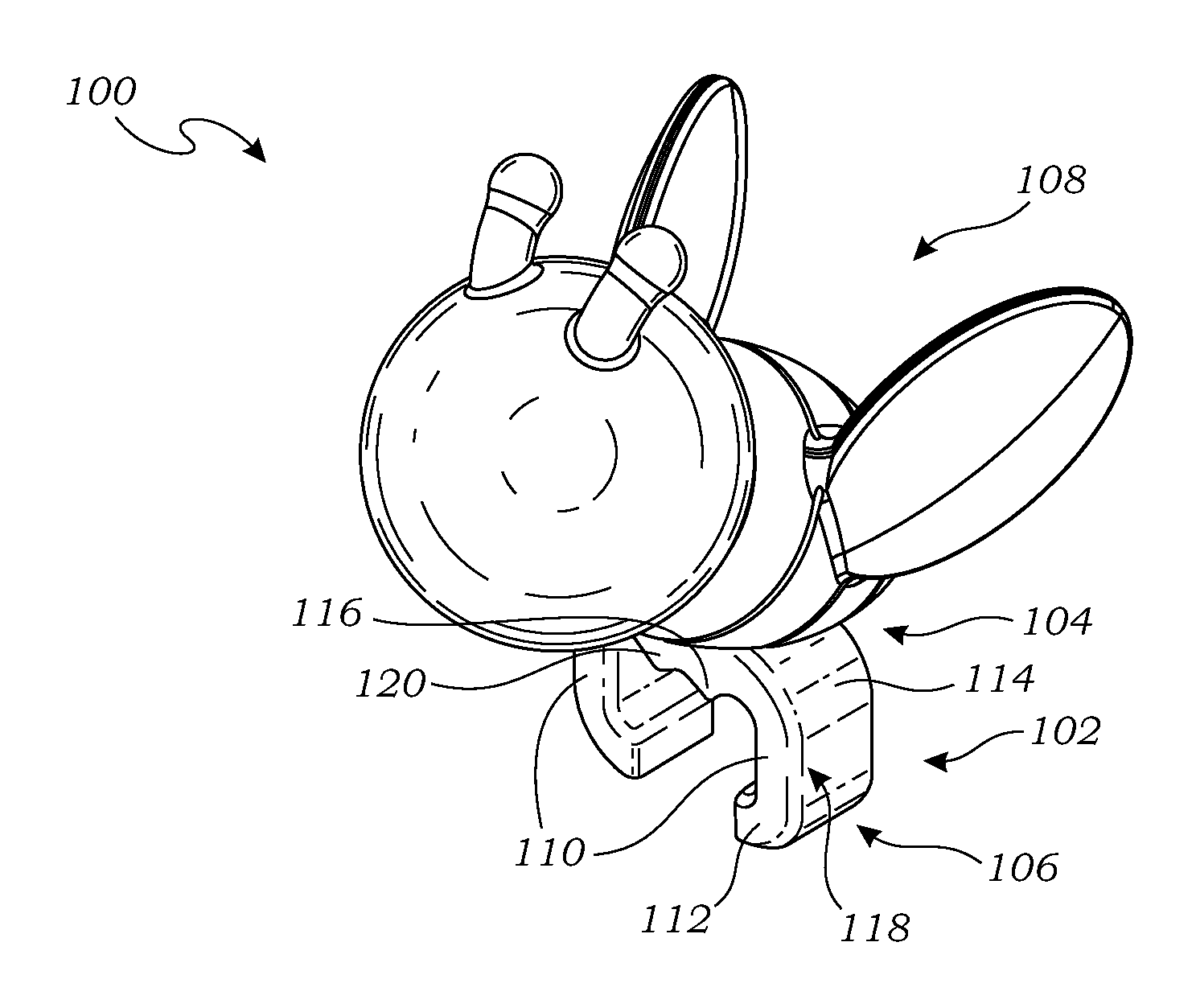
[0027]Referring now to FIG. 1, therein is shown an isometric view of the clip attachment system 100 in a The clip attachment system 100 is shown having a clip 102 having a proximal end 104 and a distal end 106.

[0028]Attached to the clip 102 is a toy 108. The toy 108 is attached to the clip 102 near the proximal end 104 of the clip 102. The toy 108 is depicted as a flying insect such as a honey bee. It is contemplated that the toy 108 can be any number of shapes and sizes including airplanes, birds, cars, trains, domesticated animals, African animals, fictional characters from cartoons or books, and other suitable forms. It is further contemplated that the clip 102 could instead attach a name tag or other identifying indicia to an item or utensil.

[0029]The distal end 106 of the clip 102 is depicted extending away from the proximal end 104 of the clip 102 with prongs 110. The prongs 110 extend downward away from the toy 108 and then terminate in curved ends 112.

[0030]The curved ends ...

second embodiment

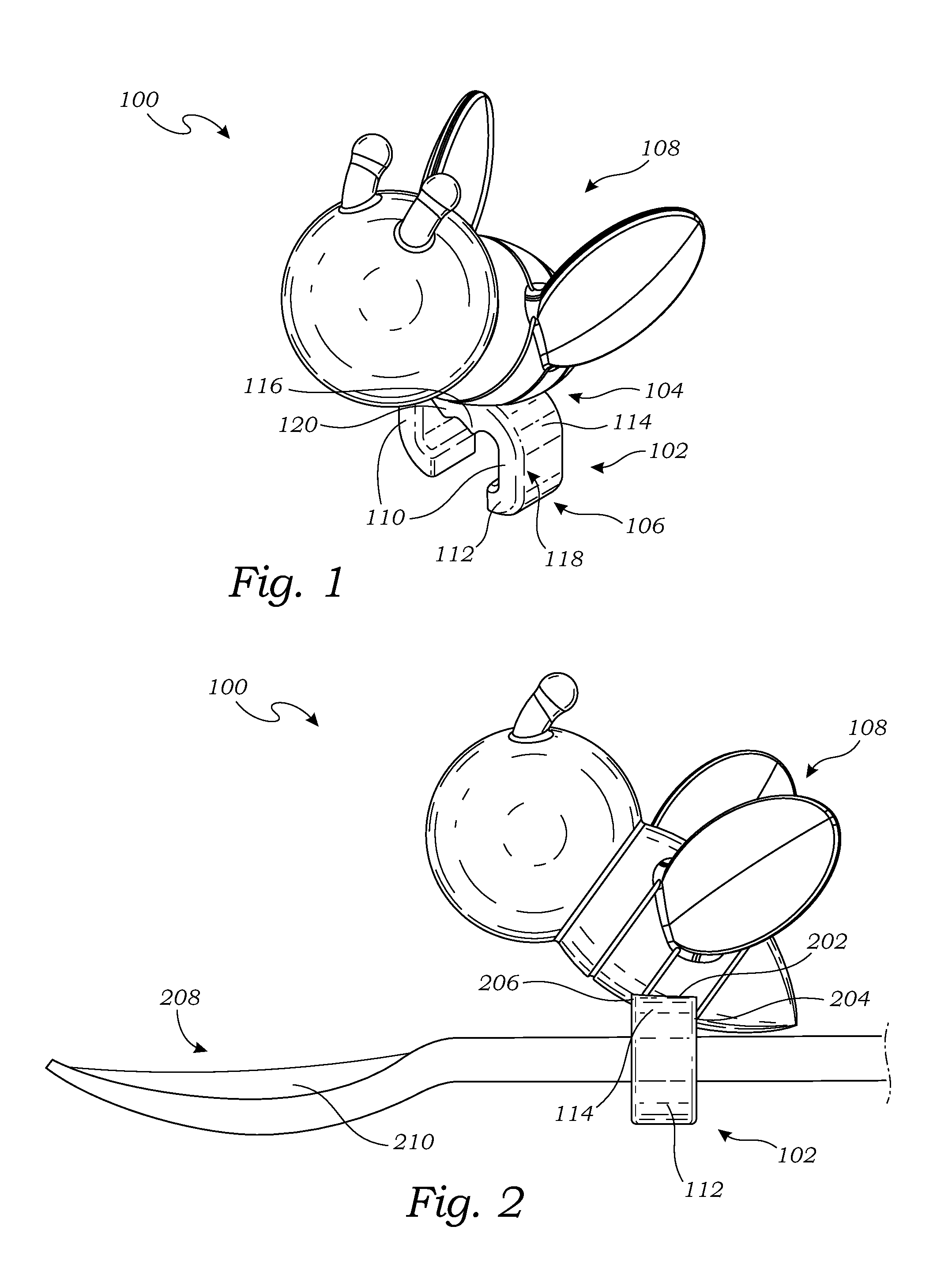
[0031]The prongs 110 are depicted as extending vertically down; however it is contemplated that the prongs 110 can be manufactured to extend down in a curved fashion similar to that depicted in FIG. 5, below. The prongs 110 are connected to the proximal end 104 of the clip 102 with shoulders 114. The shoulders 114 curve down and away from a middle portion 116 of the proximal end 104.

[0032]The shoulders 114 connect the proximal end 104 to the prongs 110 on sides 118 of the clip 102. The side 118 are depicted as flat. It is contemplated that the side 118 can include curved surfaces and other suitable shapes as well.

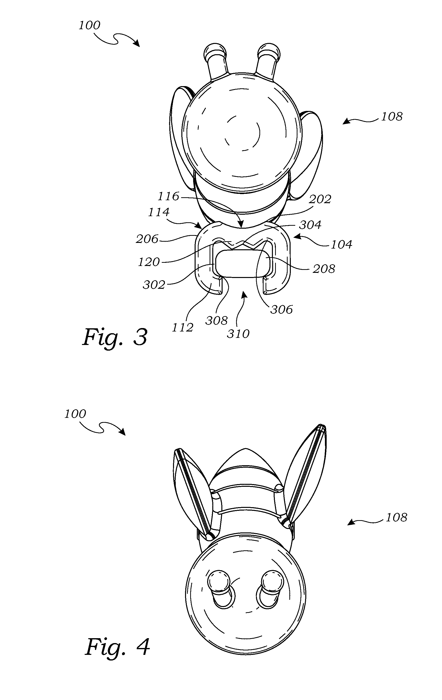
[0033]Near the middle portion 116 of the proximal end 104 the clip 102 includes proximal extensions 120. The proximal extensions 120 extend down away from the proximal end 104 near the middle portion 116 toward the distal end 106.

[0034]It has been discovered that the proximal extensions 120 and the curved ends 112 of the clip 102 enable the clip attachment system 100 to be ...

third embodiment

[0056]Referring now to FIG. 6, therein is shown an isometric view of the clip attachment system 600 in a The clip attachment system 600 is shown having a clip 602 having a proximal end 604 and a distal end 606.

[0057]Attached to the clip 602 is a toy 608. The toy 608 is attached to the clip 602 near the proximal end 604 of the clip 602. The toy 608 is depicted as a flying insect such as a honey bee. It is contemplated that the toy 608 can be any number of shapes and sizes including airplanes, birds, cars, trains, domesticated animals, African animals, fictional characters from cartoons or books, and other suitable forms. It is further contemplated that the clip 602 could instead attach a name tag or other identifying indicia to an item or utensil.

[0058]The distal end 606 of the clip 602 is depicted extending away from the proximal end 604 of the clip 602 with prongs 610. The prongs 610 extend downward away from the toy 608 and then terminate in curved ends 612.

[0059]The curved ends ...


PUM

PropertyMeasurementUnit
elasticaaaaaaaaaa
shapeaaaaaaaaaa
areaaaaaaaaaaa

Abstract

A clip attachment system and method of manufacture can include: a proximal end; a first prong and a second prong, the first prong and the second prong extending from sides of the proximal end; a proximal extension extending from a middle portion of the proximal end between and spaced apart from the first prong and the second prong, and the proximal extension extending further from the proximal end than all portions of the first prong and the second prong that are in direct contact with the proximal end; a first intermediate extension extending from the first prong toward the second prong and a second intermediate extension extending from the second prong toward the first prong; and wherein the first prong terminates in a first curved end that extends toward and is spaced apart from a second curved end of the second prong.

Description

CROSS-REFERENCE TO RELATED APPLICATIONS[0001]This is a Divisional of U.S. patent application Ser. No. 14 / 290,897 filed May 29, 2014 and claims priority benefit to all common subject matter. The content of this application is incorporated herein by reference.TECHNICAL FIELD[0002]This disclosure relates to clips for mechanical attachment, more particularly a clip for attaching to a utensil.BACKGROUND[0003]Utensils represent a large mature market in the United States. One area of the utensil market provides solutions for children while they are eating. Keeping a child entertained and sufficiently distracted while eating is an area of active product development and a point on which products are being effectively differentiated.[0004]To compete successfully in this market a product must offer both high levels of functionality, and versatility, competitive cost, and ease of use. Many products on the market provide a toy permanently affixed to the end of a handle of a utensil. This develop...

Claims


Application Information

Patent Timeline
Patent Type & Authority Applications(United States)
IPC IPC(8): A63H33/00F16B2/22
CPCF16B2/22A63H33/00
Inventor OI, DICKSON
Owner OI DICKSON
Why Eureka
Try Eureka