Heat dissipation structure for LED explosion-proof lamp

Inactive Publication Date: 2016-01-21
LI HONG SCI & TECH
View PDF2 Cites 7 Cited by
  • Summary
  • Abstract
  • Description
  • Claims
  • Application Information

AI Technical Summary

Benefits of technology

[0005]The primary object of the present invention is to solve the problem of the conventional technique of explosion-proof lamp set by collaborati

Problems solved by technology

However, the lifespan of LED significantly shortens under high temperature.
When the LED is in use it generates waste heat which cannot be dispersed through infrared ray radiatio

Method used


Image

  • Heat dissipation structure for LED explosion-proof lamp
  • Heat dissipation structure for LED explosion-proof lamp
  • Heat dissipation structure for LED explosion-proof lamp

Examples


first embodiment

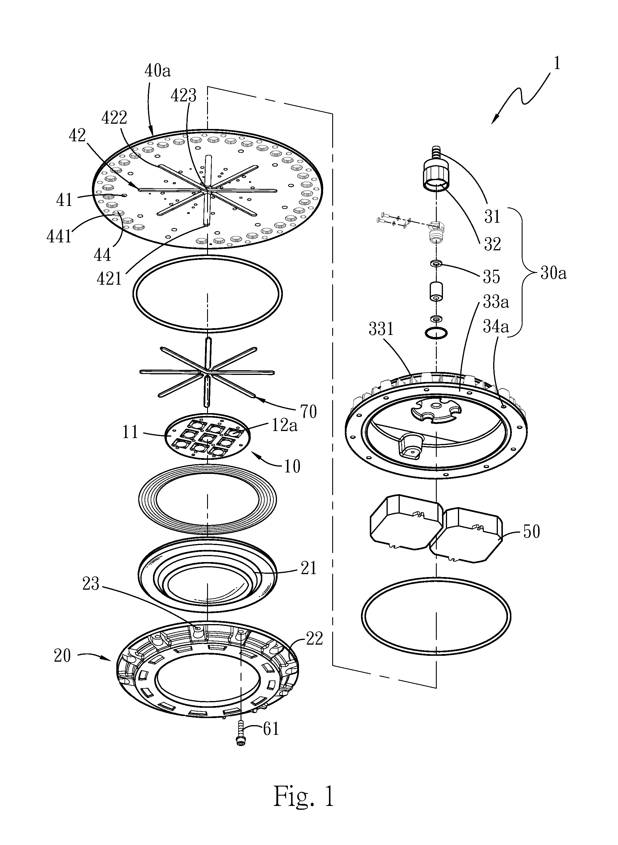
[0036]More specifically, in the invention, the illumination module 10 includes a base 11 and at least one LED 12a located on the base 11. The base 11 has a circuitry (not shown in the drawings) laid thereon to form electric connection with the LED 12a. The invention can include a single LED 12a or a plurality of LEDs 12a, depending on illumination requirements.

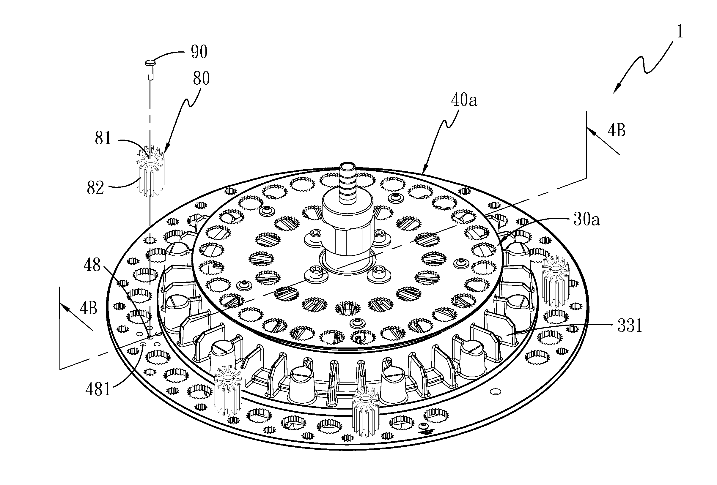
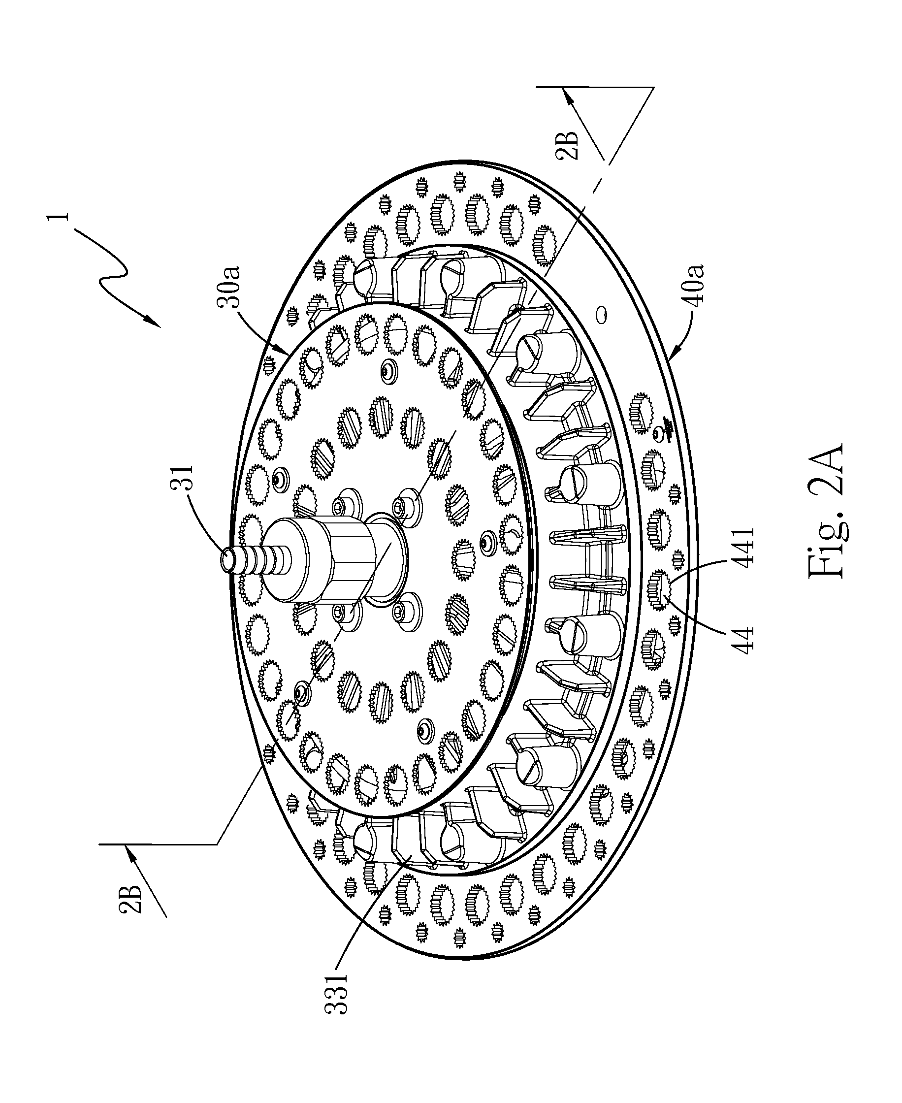
[0037]The heat conduction disk 40a is installed on the base 11 and has a plurality of installation holes 41 formed along the circumference of the base 11 to connect to other structural elements, and can be made of metal which has a higher heat conduction efficiency and is corrosion resistant, such as 6061 aluminum alloy, 6063 aluminum alloy or the like.

[0038]The window frame shell 20 is located at one side of the illumination module 10 where the LED 12a is located, and includes a light permeable portion 21 corresponding to each LED 12a, a window frame 22 encircled the light permeable portion 21 and a plurality of window frame ...

second embodiment

[0052]Also referring to FIG. 7, in the second embodiment the heat conduction disk 40b further includes two panels 45 which are constructed same. FIG. 7 illustrates only one of the panels 45 as an example.

[0053]Each panel 45 has an indented clamp portion 46 at one side facing the other panel 45. The clamp portion 46 includes a plurality of wedge troughs 461 originated from the center of the heat conduction disk 40b and extended radially from the center thereof. The LED explosion-proof lamp heat dissipation structure 1 further includes a plurality of heat conduction materials 70 located between the two clamp portions 46. In this embodiment the heat conduction materials 70 are clamped by the panels 45 and confined in the clamp portions 46. Waste heat generated by the LED 12b in operation can be transmitted from the base 11 to the heat conduction disk 40b, then conducted via the heat conduction materials 70 to other portions of the heat conduction disk 40b, so that the heat originally c...


PUM


Abstract

A heat dissipation structure for an LED explosion-proof lamp includes an illumination module, a heat conduction disk, a window frame shell and a lamp set shell. The illumination module includes a base and at least one light-emitting diode. The heat conduction disk includes a plurality of installation holes. The window frame shell includes a light permeable portion, a window frame and a plurality of window frame connection holes. The lamp set shell includes a casing portion and a plurality of lamp set connection holes. Each compact member presses and holds the window frame shell and the lamp set shell. The heat conduction disk has a heat conduction zone formed on a projection location of the window frame shell and the lamp set shell, and a cooling zone encircled the heat conduction zone at an outer side to perform heat exchange with external air.

Description

FIELD OF THE INVENTION[0001]The present invention relates to a LED explosion-proof lamp heat dissipation structure and particularly to a LED explosion-proof lamp heat dissipation structure that provides improved cooling efficacy and also is explosion proof.BACKGROUND OF THE INVENTION[0002]Light-emitting diode (LED in short hereinafter) has many advantages, such as smaller size, faster response speed, longer lifespan and the like. In the past LED mainly is used as the light source of backlight panels of screens. Upon constant research and improvement, now illumination lamp sets using the LED as the light source have been developed. However, the lifespan of LED significantly shortens under high temperature. When the LED is in use it generates waste heat which cannot be dispersed through infrared ray radiation, but can only be dispersed through conduction. Hence the general LED lamp set usually is connected to heat conductive material to reduce thermal resistance to conduct the waste h...

Claims


Application Information

Patent Timeline
IPC IPC(8): F21V29/83F21V29/507F21V29/74
CPCF21V29/83F21Y2101/02F21V29/507F21V29/74F21V23/003F21V25/12F21V29/773F21Y2115/10
Inventor CHIEN, MING-TIENJUAN, CHING-YUANJUAN, YI-HUNGCHANG, HAN-WENJUAN, CHENG-LUNG
Owner LI HONG SCI & TECH
Why Eureka
Try Eureka