Spark Arrestor and Methods Associated Therewith

a technology of spark arrestor and spark trap, which is applied in the direction of machine/engine, lighting and heating apparatus, separation process, etc., can solve the problems of increasing the burning, shortening the life of the ember, and devices sometimes failing to adequately serve as spark arrestors

Active Publication Date: 2016-01-28
MCDANIEL STEPHEN
View PDF5 Cites 2 Cited by
  • Summary
  • Abstract
  • Description
  • Claims
  • Application Information

AI Technical Summary

Problems solved by technology

This is similar to blowing on a coal, which increases the burning thereby shortening the life of the ember.
However, these devices sometimes fail to adequately serve as a spark arrestor.
For example, with the system that uses vanes, the systems that are currently on the market arc not as effective an larger / higher mass particles that burn longer because the air is exhausted directly out the other side, often allowing the spark to pass from one side of the arrestor to the other.
Systems that use a cone tend to constrict the air too much because these systems generally have a smaller inlet duct, which allows the spark / ember to stay alight too long due to inadequate ventilation / oxygen in the system.
Systems, which contain vanes tend to also release the exhaust too rapidly.
Moreover, most of the currently existing systems do not allow for easy cleaning of the system, which means that combustible materials may build up in the system.
If an ember or spark ignites the combustible material one may got an explosion (for example, an exhaust system backfire).

Method used


Image

  • Spark Arrestor and Methods Associated Therewith
  • Spark Arrestor and Methods Associated Therewith
  • Spark Arrestor and Methods Associated Therewith

Examples


Embodiment Construction

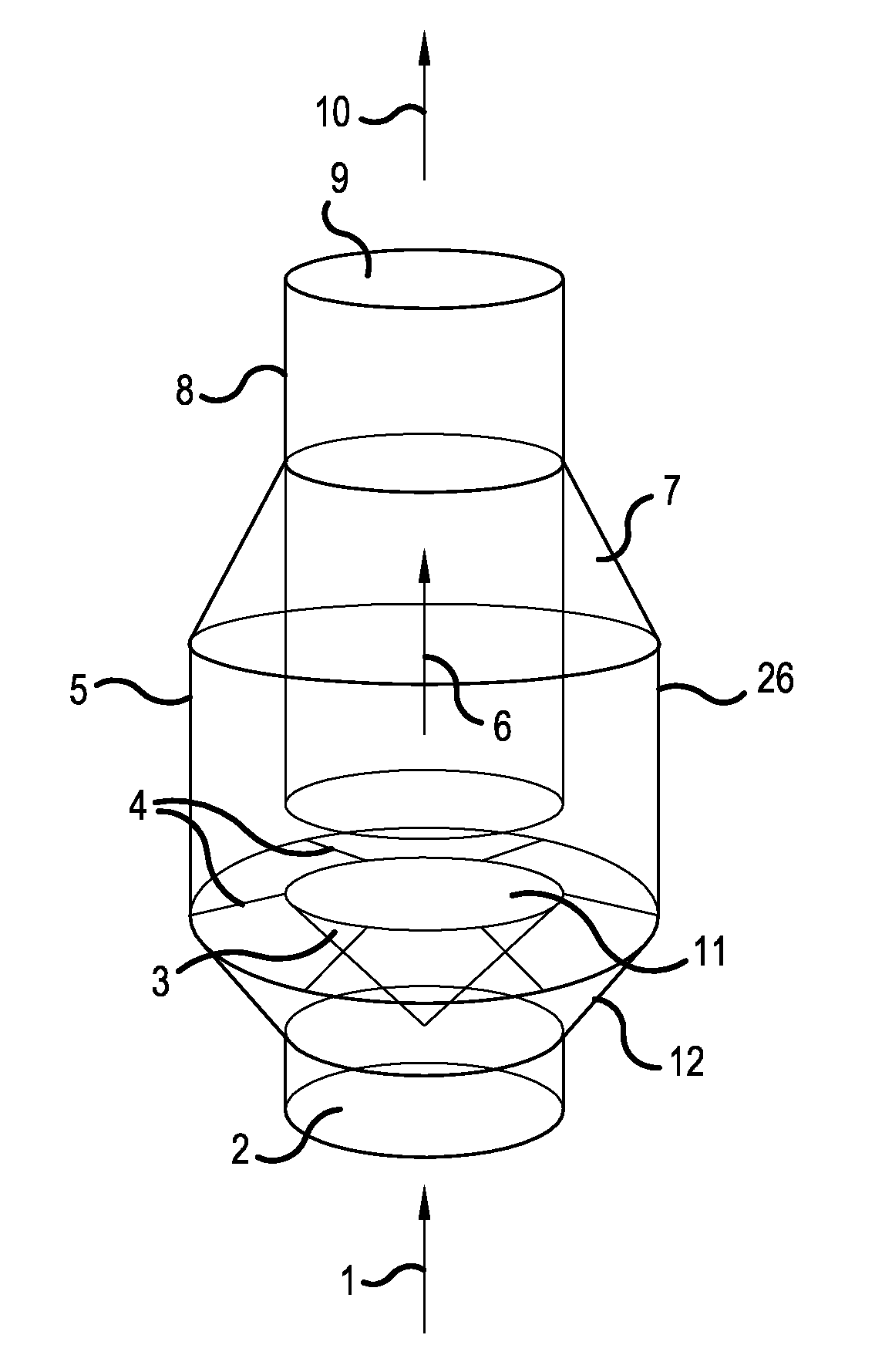
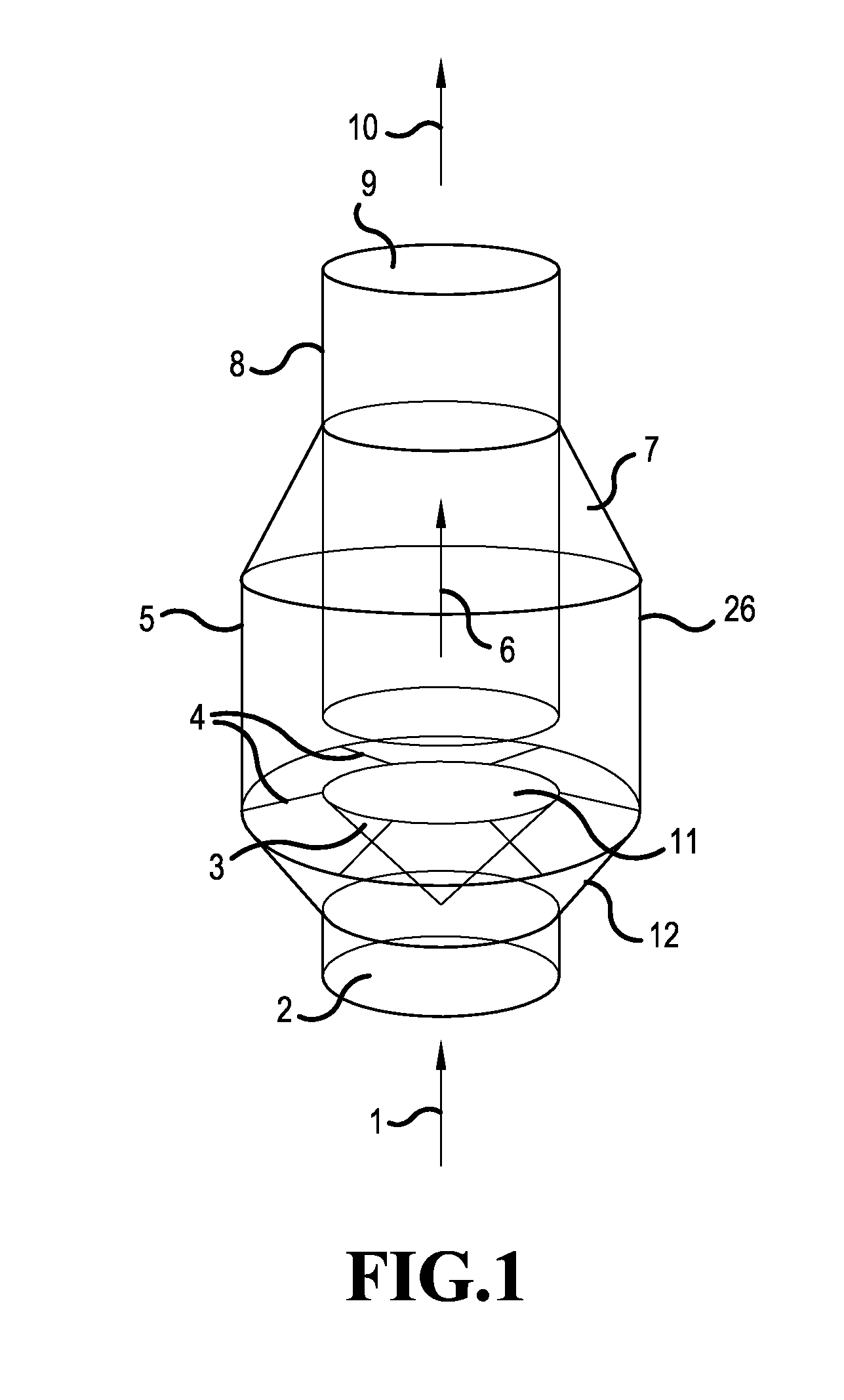
[0012]The present invention relates to a spark arrestor / trap that comprises a plurality of features that allows sparks / embers to be more effectively extinguished. In an embodiment, the spark trap / arrestor of the present invention has at least two of vanes, conical devices and to-turns that allows for sufficient oxygen and a tortured path that is sufficiently long so as to effectively extinguish sparks and / or embers that enter the system. In an embodiment, the present invention relates to a system that comprises all of vanes, conical devices and u-turns that allows for sufficient oxygen and a tortured path that is sufficiently long so as to effectively extinguish sparks and / or embers that enter the system. In an embodiment, the various parts of the spark arrestor can be separated allowing for easy cleaning of the system.

[0013]In an embodiment, the present invention will be explained with reference to FIG. 1. However, it is contemplated and therefore within the scope of the invention ...


PUM

PropertyMeasurementUnit
volumeaaaaaaaaaa
diameteraaaaaaaaaa
flammableaaaaaaaaaa

Abstract

The present invention relates to spark traps/arrestors that are unproved relative to those that currently exist. For example, the present invention relates to a spark arrestor/trap that comprises a plurality of features that allows sparks/embers to be more effectively extinguished. The spark trap/arrestor of the present invention has at least two of vanes, conical devices and u-turns that allows for sufficient oxygen and a tortured path that is sufficiently long so as to effectively extinguish sparks and/or embers that enter the system. Alternatively, the system relates to a spark arrestor that comprises all of vanes, conical devices and u-turns that allows for sufficient oxygen and a tortured path that is sufficiently long so as to effectively extinguish sparks and/or embers that enter the system. In one embodiment, the various pans of the spark arrestor can he separated allowing for easy cleaning of the system.

Description

[0001]The present invention claims priority under 35 USC 119(e) to U.S. Provisional Application No. 62 / 028,898 filed Jul. 25, 2014, the entire contents of which is incorporated by reference in its entirety.FIELD OF THE INVENTION[0002]The present invention relates to spark traps / arrestors that are improved relative to those that currently exist.BACKGROUND OF THE INVENTION[0003]Spark arrestors have been used in a plurality of technologies including steam engines, internal combustion engines, building flues or chimneys, in various types of electrical equipment, and on automotive / motor vehicle exhaust equipment. They also find use in welding technologies.[0004]A spark arrestor is any device which prevents the emission of flammable debris from reaching combustion sources. Spark arrestors are used for a plurality of reasons, for example, they may play a critical role in the prevention of dust collection, the prevention of wildland fires and the prevention of the ignition of explosive atmo...

Claims


Application Information

Patent Timeline
Patent Type & Authority Applications(United States)
IPC IPC(8): A62C4/04
CPCA62C4/04F23J15/022B01D46/0093F01N2230/06F01N3/06
Inventor MCDANIEL, STEPHEN
Owner MCDANIEL STEPHEN
Why Eureka
Try Eureka