Systems for producing solid carbon by reducing carbon oxides

a carbon oxide and carbon dioxide technology, applied in the field of systems and reactors, can solve the problems of cost, availability, and quality limit the wide industrial use of this material, and the carbon is one of the more expensive allotropes of carbon

Inactive Publication Date: 2016-01-28
SEERSTONE
View PDF1 Cites 11 Cited by
  • Summary
  • Abstract
  • Description
  • Claims
  • Application Information

AI Technical Summary

Benefits of technology

[0007]In some embodiments, an apparatus for producing carbon nanoparticles by reducing carbon oxide compounds using a reducing agent includes a reactor configured to receive a dried recycle gas stream, a fresh feed gas stream comprising carbon oxide, and a gaseous reducing agent. The reactor includes at least one mixing means configured to mix the reagents to form a combined gaseous feed stream, a first heat exchanger configured to heat the combined gaseous feed stream to a first temperature, at least one heater configured to further heat the combined gaseous feed stream to a temperature higher than the first temperature, and a reaction vessel configured to receive the heated combined gaseous feed stream. The reaction vessel is configured to maintain predetermined reaction conditions of temperature and pressure, and has an output configured to deliver a tail gas stream to the first heat exchanger. The reaction vessel and other associated vessels and piping that may be subjected to metal dusting conditions in the course of normal service may be designed to prevent metal dusting such as, for example, by using high-chromium steel or a ceramic lining.

Problems solved by technology

Currently, CNTs are one of the more expensive allotropes of carbon, and the cost, availability, and quality limit broad industrial uses of this material.

Method used


Image

  • Systems for producing solid carbon by reducing carbon oxides
  • Systems for producing solid carbon by reducing carbon oxides
  • Systems for producing solid carbon by reducing carbon oxides

Examples


example 1

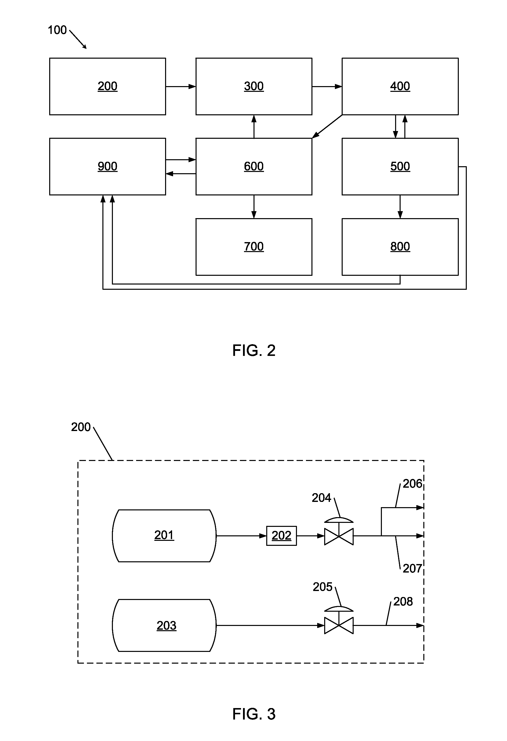
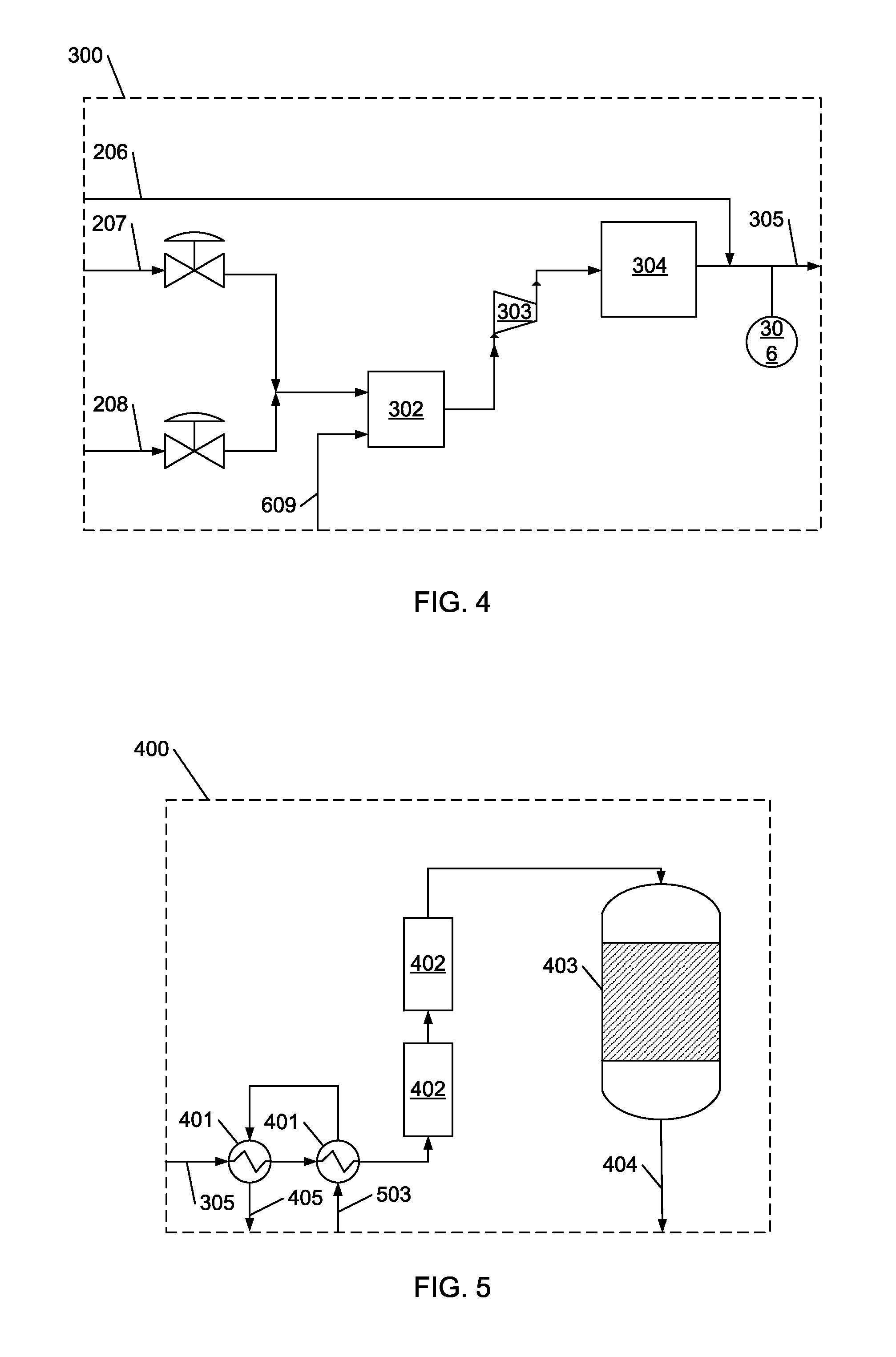
[0090]FIG. 2 depicts one embodiment of a system 100 for production of solid carbon products. Aspects of this embodiment are shown in further detail in FIGS. 3 through 10. The system 100 typically includes a gas supply subsystem 200, a gas handling subsystem 300, a reactor subsystem 400, a product separation subsystem 500, a water separation subsystem 600, a water treatment subsystem 700, a product packaging subsystem 800, and a utilities subsystem 900 (each shown in more detail in FIGS. 3 through 10). In FIGS. 2 through 10, solid arrows indicate the flow of materials (gas, liquid, etc.). In the system 100, information also flows within and between various subsystems. The subsystems may be modified or combined, or may be added to additional subsystems as fitting desired production processes. The subsystems may be positioned to improve operating economics and to make efficient use of space in a process facility. The subsystems may also include various instruments or equipment, such as...

example 2

[0103]FIG. 11 depicts another system 1100 for producing solid carbon products of various morphologies. The system 1100 includes a gas supply subsystem 1200, a gas handling subsystem 1300, a fluidized-bed reaction subsystem 1400, a product separation and packaging subsystem 1500, a water treatment subsystem 1600, and a venting subsystem 1700 (each shown in more detail in FIGS. 12 through 17). In the system 1100, solid arrows indicated the flow of materials (gas, liquid, etc.). In FIGS. 11 through 17, solid arrows indicate the flow of materials (gas, liquid, etc.). Information also flows within and between various subsystems. The subsystems may be modified or combined, or may be added to with additional subsystems as fitting desired production processes. The subsystems may be positioned to improve operating economics and to make efficient use of space in a process facility. The subsystems may also include various instruments or equipment, such as valves, transducers, flow meters, swit...

example 3

[0113]FIG. 18 depicts another system 1800 for producing solid carbon products of various morphologies. The system 1800 includes a gas supply subsystem 1900, a gas handling subsystem 2000, a reactor subsystem 2100, a product separation subsystem 2200, a water separation subsystem 2300, a water treatment subsystem 2400, a product packaging subsystem 2500, and a utilities subsystem 2600 (each shown in more detail in FIGS. 19 through 26). In FIGS. 18 through 26, solid arrows indicate the flow of materials (gas, liquid, etc.). Information also flows within and between various subsystems. The subsystems may be modified or combined, or may be added to with additional subsystems as fitting desired production processes. The subsystems may be positioned to improve operating economics and to make efficient use of space in a process facility. The subsystems may also include various instruments or equipment, such as valves, transducers, flow meters, switches, controllers, computers, etc. The gas...


PUM

PropertyMeasurementUnit
temperatureaaaaaaaaaa
grain sizeaaaaaaaaaa

Abstract

An apparatus for producing solid carbon and water by reducing carbon oxides with a reducing agent in the presence of a catalyst includes a reactor configured to receive reaction gas comprising at least one carbon oxide, at least one reducing agent, and water. The apparatus includes at least one mixing means configured to mix the reagents to form a combined feed, a first heat exchanger configured to heat the combined feed, at least one heater configured to further heat the combined feed, and a reaction vessel configured to receive the combined feed. The reaction vessel is configured to contain a catalyst, to maintain predetermined reaction conditions of temperature and pressure, and has an output configured to deliver a tail gas to the first heat exchanger. The system also includes a product separator, a water separation unit, and a product packaging unit.

Description

PRIORITY CLAIM[0001]This application claims the benefit of the filing date of U.S. Provisional Patent Application Ser. No. 61 / 788,474, filed Mar. 15, 2013, for “Systems for Producing Solid Carbon by Reducing Carbon Oxides,” the contents of which are incorporated herein by this reference.FIELD[0002]Embodiments of the present disclosure relate to reactors, systems, and methods for forming products from a reactive gas in the presence of a catalyst. For example, methods disclosed herein may be used to form various allotropes and morphologies of solid carbon, including carbon nanotubes.BACKGROUND[0003]Continuous production of solid products from reactive gases typically entails reacting the reactive gases in the presence of a catalyst in such a way that the solid products are elutriated from the surface of the catalyst. The solid products are thus swept away from the catalyst and subsequently harvested in a suitable process or series of processes for removing particulates from reaction t...

Claims


Application Information

Patent Timeline
Patent Type & Authority Applications(United States)
IPC IPC(8): C01B31/02B01J19/00B01J19/18
CPCC01B31/02B01J2219/00074B01J19/0066B01J19/18C01B32/05B01J2219/00103B65B35/10B65B39/001
Inventor NOYES, DALLAS, B.
Owner SEERSTONE
Why Eureka
Try Eureka