

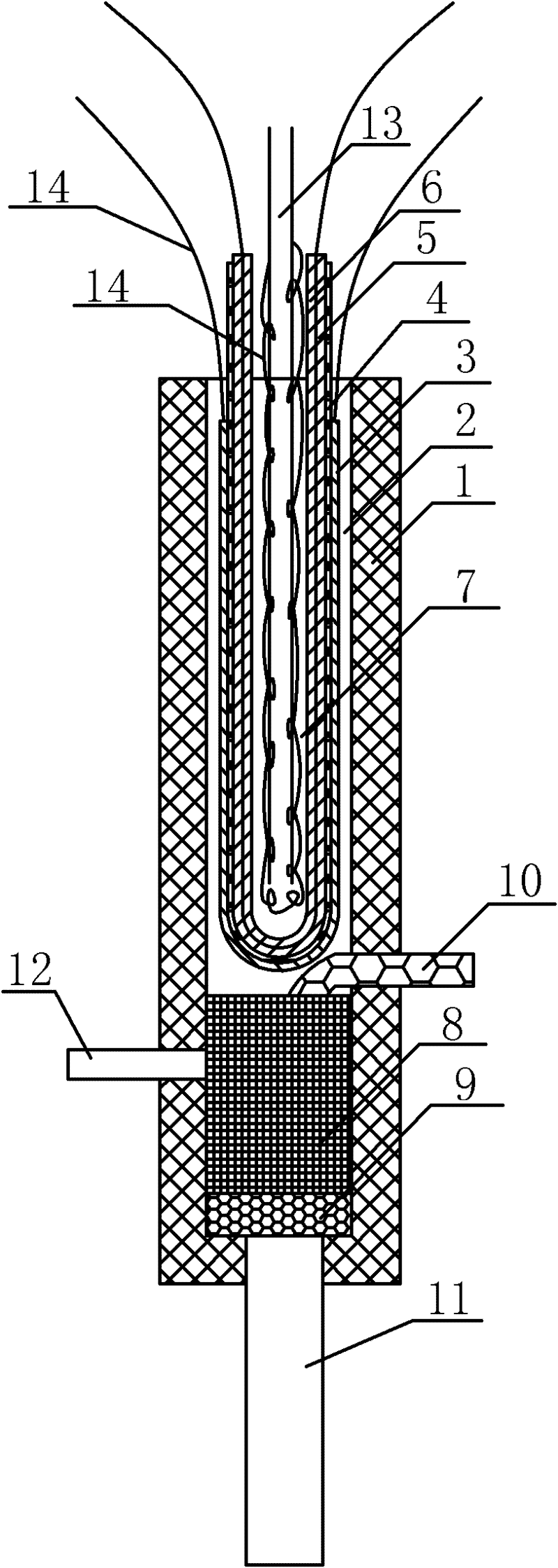
A cathode-supported direct carbon fuel cell
A cathode support and fuel cell technology, which is applied to fuel cell parts, molten electrolyte fuel cells, electrolyte holding devices, etc., can solve the problems of limited fuel diversity, difficult operation, and low fuel supply, and achieve the goal of adding Easy to operate, realize the effect of diversification and high energy efficiency
- Summary
- Abstract
- Description
- Claims
- Application Information
AI Technical Summary
Problems solved by technology
Method used
Image

Examples
Embodiment 1
[0031] The cathode-supported direct carbon fuel cell was prepared by dipping molding method, in which: the material of the anode layer was NiO-YSZ composite material, the material of the electrolyte layer was YSZ, the material of the cathode active layer was the composite material of LSM-YSZ, and the material of the cathode support layer was The material is LSM; the preparation process includes:
[0032] (1) Add organic solvent, dispersant, pore-forming agent, binder, plasticizer to ball milling and mixing in each functional layer material powder to obtain the slurry of each functional layer, and vacuumize the slurry;
[0033] (2) Immerse the mold tube in the cathode slurry, repeat the impregnation and drying process until the required thickness, and pre-fire the obtained cathode support and active layer green body at a certain temperature after demoulding, and then impregnate the electrolyte slurry to form a cathode / electrolyte composite After co-sintering, impregnate the ano...
Embodiment 2
[0052] The difference between this embodiment and embodiment 1 is that the material of the anode layer is a composite material of NiO-SSZ, the material of the electrolyte layer is SSZ, the material of the cathode active layer is a composite material of LSM-SSZ, and the material of the cathode support layer for LSM.
[0053] All the other contents are described in Example 1.
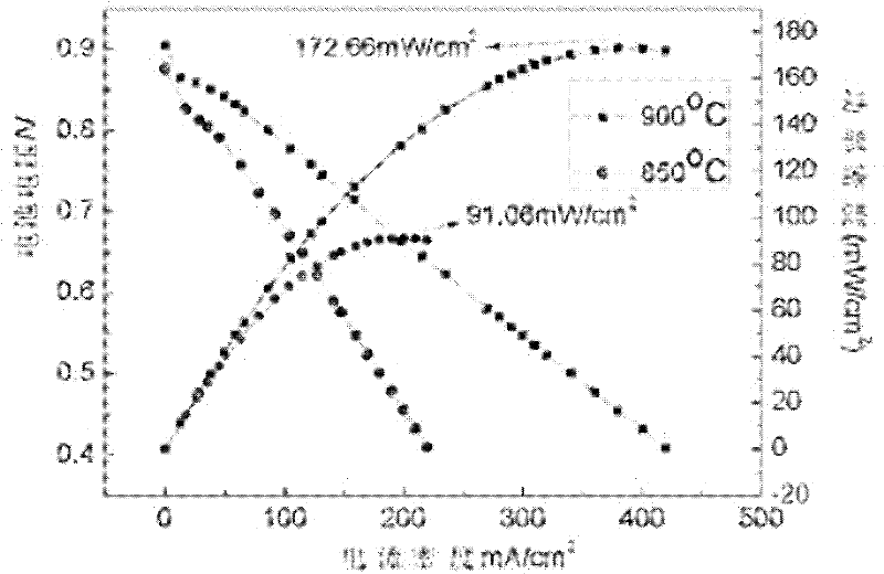
[0054] image 3 The discharge performance curve of the cathode-supported direct carbon fuel cell prepared for this example is shown by image 3 It can be seen that directly using solid carbon as fuel, the open circuit voltage is between 0.88-0.91, and at 900°C and 850°C, the power density is 172.66 and 92.06mW / cm respectively 2 . Compared with Example 1, the electrochemical performance has been significantly improved. This is due to the higher electrical conductivity and catalytic activity of SSZ compared to YSZ.
[0055] Figure 4 The cross-sectional SEM photo of the cathode-supported direct carbon...
Embodiment 3
[0057] The difference between this embodiment and embodiment 2 is that the material of the anode layer is NiO-GDC composite material with better catalytic performance, and the rest of the content is the same as that of embodiment 1.
PUM
| Property | Measurement | Unit |
|---|---|---|
| Power density | aaaaa | aaaaa |
| Power density | aaaaa | aaaaa |
Abstract
Description
Claims
Application Information