Heat exchanger and manufacturing method thereof

a technology of heat exchanger and heat exchanger body, which is applied in the direction of heat exchanger fins, tubular elements, stationary conduit assemblies, etc., can solve the problems of affecting the heat exchange performance of the heat exchanger, so as to achieve enhanced heat exchange performance and easy stagnation

Active Publication Date: 2016-01-28
DENSO CORP
View PDF9 Cites 4 Cited by
  • Summary
  • Abstract
  • Description
  • Claims
  • Application Information

AI Technical Summary

Benefits of technology

[0012]It is another objective of the present disclosure to provide a heat exchanger capable of obtaining a satisfactory heat exchange performance while reducing a fin width.
[0014]When viewed in the one direction, the length at the tip end of the louver becomes shorter with increase of the louver height. Therefore, assuming that the fin is shaped, for example, by roller shaping which is a typical fin shaping method, the cutting blades to shape the respective louvers come into contact with a raw material of the fin, and a lag in contact starting time of the cutting blades becomes smaller. For example, multiple louver-shaping cutting blades start to cut in the raw material of the fin substantially at the same time. The heat exchanger thus includes a fin in which unnecessary shape deformation is limited in shaping, and therefore a satisfactory heat exchange performance can be obtained.
[0016]According to the discourse as above, the shaping rollers including multiple louver-shaping cutting blades having different cutting blade heights are used in the fin shaping step. Hence, multiple louvers having different louver heights can be shaped. The shaping rollers include the multiple louver-shaping cutting blades in which the high cutting blade having a high cutting blade height has a short length at the cutting blade tip end in comparison with the low cutting blade having a low cutting blade height. Since the multiple louver-shaping cutting blades start to cut in the fin material at the same timing with one another, the louver-shaping cutting blades mutually cancel out pulling-in of the fin material that occurs when the louver-shaping cutting blades cut in the fin material. Hence, the present disclosure has an advantage that the fin material hardly undergoes deformation in a direction in which the louver-shaping cutting blades are aligned, namely, an axial direction of the shaping rollers.
[0019]The louver lengths of the upstream-end first louver and the upstream-end second louver are set to ⅝×LP or longer. Hence, wide clearances are secured between the upstream-end first louver and adjacent first louver and between the upstream-end second louver and adjacent second louver according to the louver lengths. The second fluid thus hardly stagnates in these clearances in which the second fluid readily stagnates otherwise when the fin width is 14 mm or shorter. Hence, a satisfactory heat exchange performance of the heat exchanger can be obtained while the heat exchanger is made more compact by reducing the width of the fin of the heat exchanger to 14 mm or shorter.
[0022]The upstream-end first louver, the downstream-end first louver, the upstream-end second louver, and the downstream-end second louver are provided so as to have a large inclination angle in comparison with the intermediate first louver and the intermediate second louver. Hence, inter-louver passages tangent to the upstream-end first louver, the downstream-end first louver, the upstream-end second louver, and the downstream-end second louver become wider. Consequently, air can be made to hardly stagnate where air generally stagnates easily, and a heat exchange performance of the heat exchanger can be enhanced.
[0024]As has been described, the passages of the first inter-louver passages on the uppermost stream side and the lowermost stream side in the air current are wider than the other first inter-louver passages. The passages of the second inter-louver passages on the uppermost stream side and the lowermost stream side in the air current are wider than the other second inter-louver passages. Consequently, air can be made to hardly stagnate where air generally stagnates easily, and a heat exchange performance of the heat exchanger can be enhanced.

Problems solved by technology

When a fin provided with the louvers not all of which have an equal louver height is processed by a typical fin shaping method, for example, roller shaping, it is anticipated that the fin undergoes unnecessary shape deformation due to a difference of the louver heights among the louvers.
The shape deformation has an influence on fin performance and an air current and may possibly become a cause of deterioration in heat exchange performance of the heat exchanger.
Further, a faulty fin may possibly be shaped.
However, a study conducted by the inventor of the present disclosure reveals that Patent Document 1 fails to explicitly describe a relation of a width of the fin in the one direction and shapes of the respective louvers provided to the fin.

Method used


Image

  • Heat exchanger and manufacturing method thereof
  • Heat exchanger and manufacturing method thereof
  • Heat exchanger and manufacturing method thereof

Examples


first embodiment

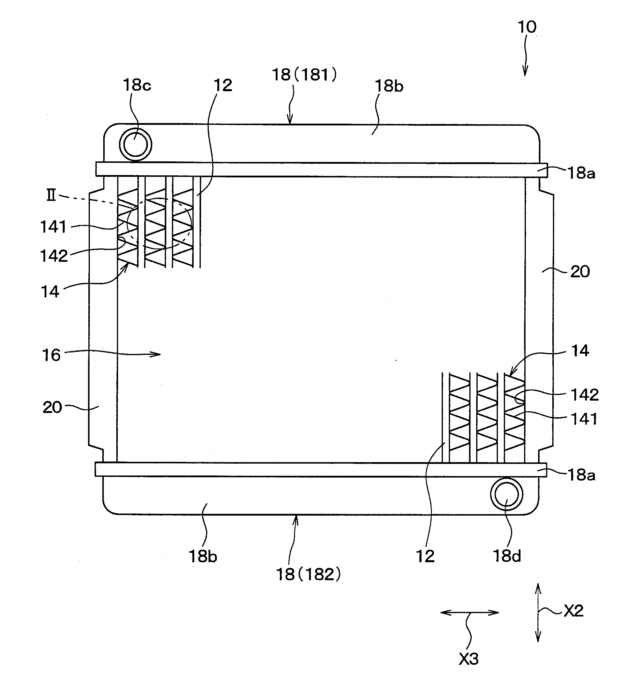
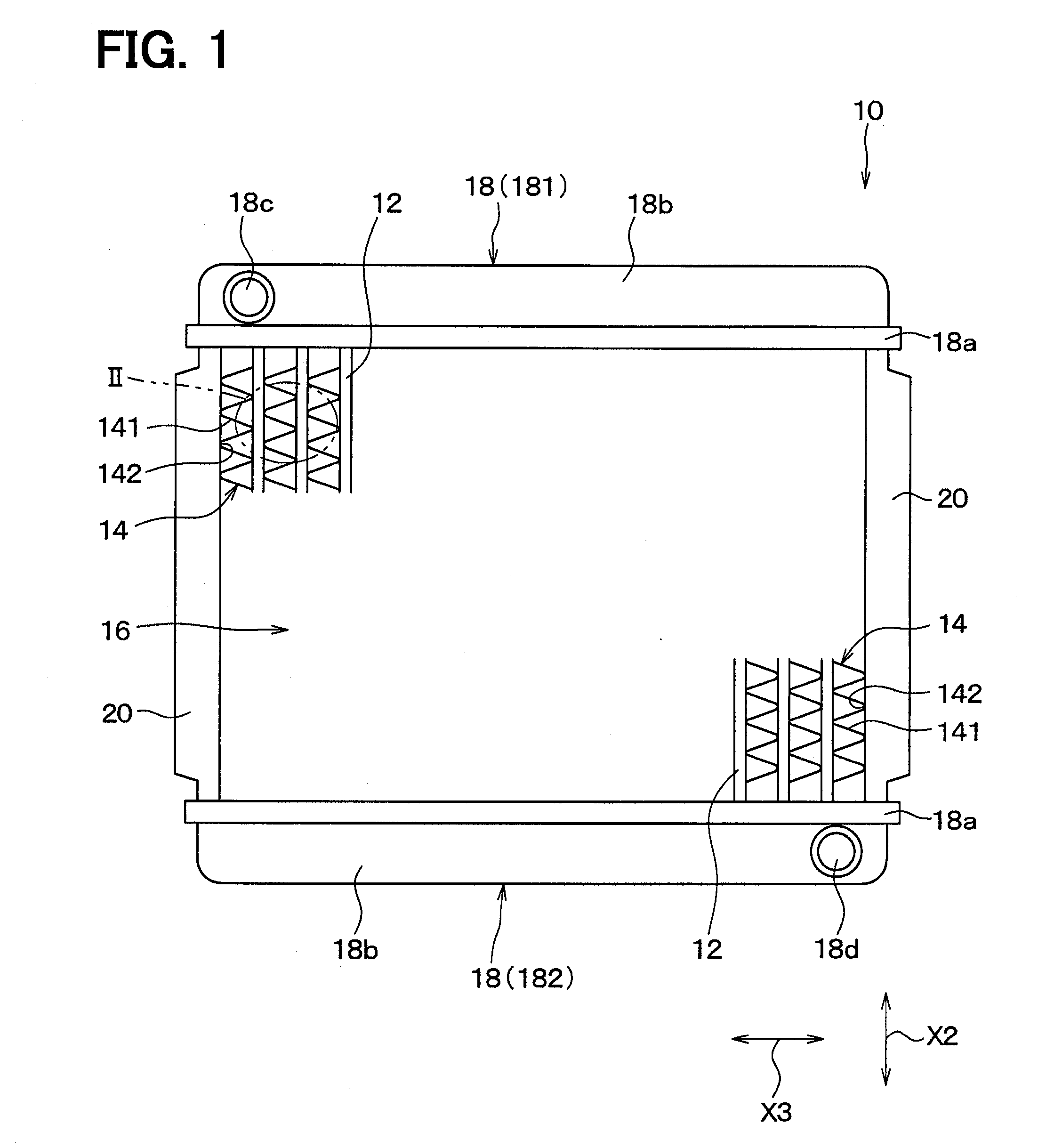
[0046]FIG. 1 is a front view of a radiator 10 of the present embodiment. The radiator 10 is, for example, a vehicle heat exchanger that cools an engine or an electric motor that runs a vehicle. The present embodiment describes an example where the present disclosure is applied to the radiator 10. It should be appreciated, however, that the present disclosure may be applied to other heat exchangers, such as an evaporator and a heater core in an air conditioner.

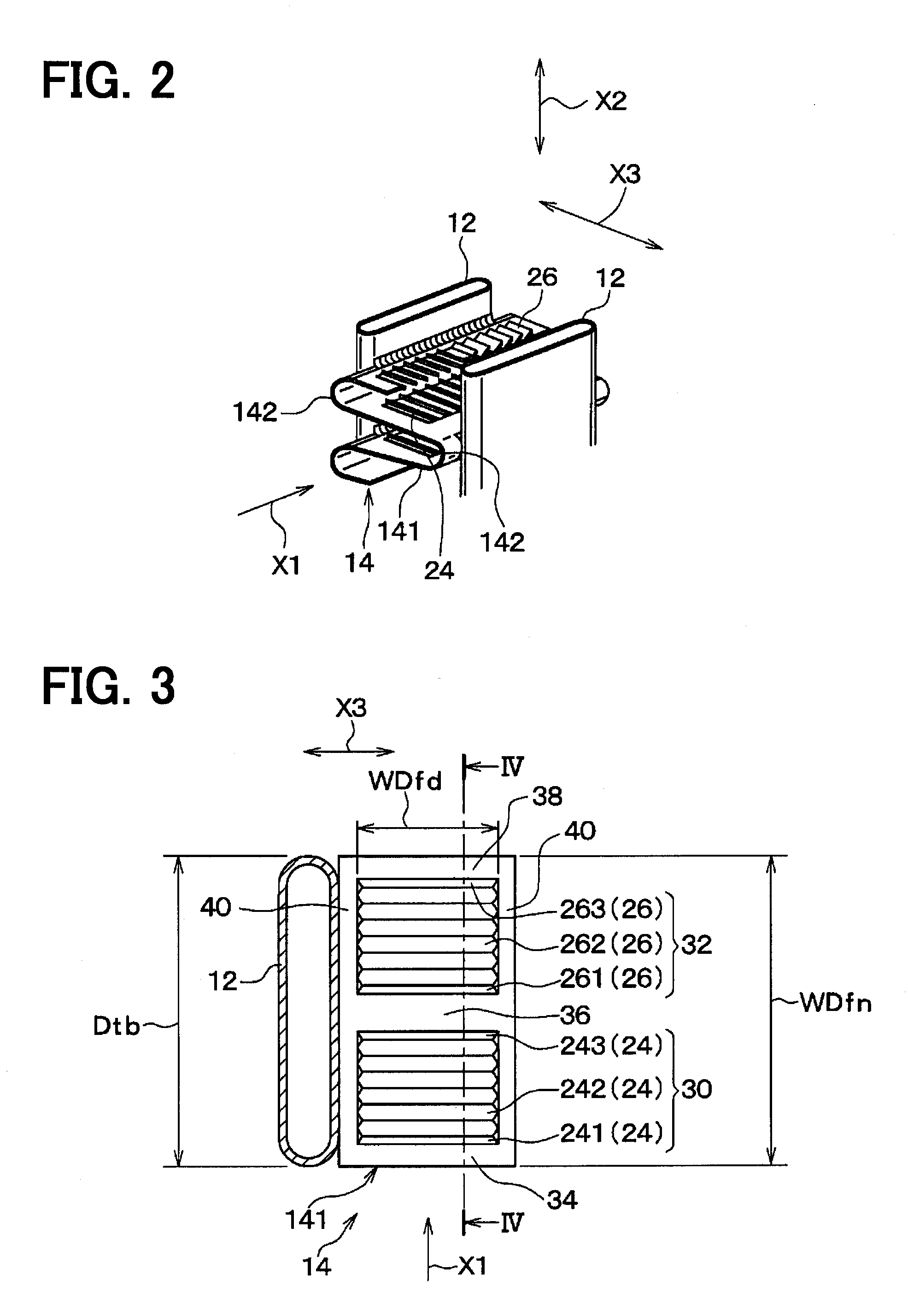
[0047]As is shown in FIG. 1, the radiator 10 includes a tube 12 which is a pipe for a coolant as a first fluid to flow. The tube 12 is formed to have a flat oval cross section so that a longitudinal diameter direction coincides with a flow direction X1 of air as a second fluid, namely, an airflow direction X1 (see FIG. 2). Also, the tube 12 includes multiple tubes 12 which are disposed parallel to one another in a horizontal direction so that a longitudinal direction coincides with a vertical direction.

[0048]Fins 14 as a heat-t...

second embodiment

[0123]A second embodiment of the present disclosure will now be described. The present embodiment will chiefly describe a difference from the first embodiment described above. Portions same as or equivalent to the counterparts of the first embodiment above are not described repetitively or described briefly.

[0124]FIG. 15 is a view corresponding to FIG. 9 of the first embodiment above, that is, an enlarged view in the part IX of FIG. 5 in the present embodiment. In the first embodiment above, the louver side-end angle θsd varies with the louver height LH, which is different in the present embodiment. In other words, as is shown in FIG. 15, louver side-end angles θsd are equal to one another in all of louvers 24 and 26 regardless of a louver height LH.

[0125]Hence, as is shown in FIG. 15, when viewed in an airflow direction X1, louver base widths WDfd of an upstream-end first louver 241 and a downstream-end first louver 243 are short in comparison with intermediate first louvers 242. T...

third embodiment

[0128]A third embodiment of the present disclosure will now be described. The present embodiment will chiefly describe a difference from the first embodiment described above. Portions same as or equivalent to the counterparts of the first embodiment above are not described repetitively or described briefly. The same applies to fourth and subsequent embodiments below.

[0129]FIG. 16 corresponds to FIG. 4 of the first embodiment above and is a sectional view of a planar portion 141 and louvers 24 and 26 of a fin 14 when viewed in a direction same as the direction of FIG. 4. In the first embodiment above, all of the first louvers 24 are parallel to one another and all of the second louvers 26 are also parallel to one another, which is different in the present embodiment.

[0130]To be more specific, as is shown in FIG. 16, an upstream-end first louver 241 and a downstream-end first louver 243 are provided so as to have a large inclination angle with respect to an airflow direction X1, namel...


PUM


Abstract

In a heat exchanger, when louvers are viewed from an airflow direction, a louver tip end width becomes shorter with increase of a louver height. A fin width of the fin is 14 mm or shorter. Airflow-end louver lengths of an upstream-end first louver, a downstream-end first louver, an upstream-end second louver, and a downstream-end second louver are “⅝×LP” or longer, where LP is a louver pitch.

Description

CROSS REFERENCE TO RELATED APPLICATION[0001]This application is based on and incorporates herein by reference Japanese Patent Applications No. 2013-029153 filed on Feb. 18, 2013, and No. 2013-029152 filed on Feb. 18, 2013.TECHNICAL FIELD[0002]The present disclosure relates to a heat exchanger including tubes and a heat-exchange promotion fin and to a manufacturing method of the heat exchanger.BACKGROUND ART[0003]An existing heat exchanger includes multiple tubes for a first fluid to flow and fins which promote heat exchange between the first fluid and a second fluid that flows around the tubes along one direction. Such a heat exchanger is disclosed, for example, in Patent Document 1. In the heat exchanger of Patent Document 1, each fin includes a plate-like planar portion along the one direction and multiple louvers which are parallel to one another and twisted up so as to incline with respect to the planar portion.[0004]The second fluid flows a clearance between every pair of the a...

Claims


Application Information

Patent Timeline
Patent Type & Authority Applications(United States)
IPC IPC(8): F28F1/12
CPCF28F1/128F28D1/05366F28F2215/08
Inventor MABUCHI, SHINTASUGITO, HAJIMEOTA, HIDEYUKIITOU, MASATOOU, U
Owner DENSO CORP
Why Eureka
Try Eureka