Thin-film resistive-based sensor

a resistive-based sensor and thin film technology, applied in the direction of resistance/reactance/impedence, heat measurement, instruments, etc., can solve the problems of poor performance of resistive-based sensors, low stability, and limited use of these sensors for various applications

Active Publication Date: 2016-01-28
BREWER SCI
View PDF7 Cites 31 Cited by
  • Summary
  • Abstract
  • Description
  • Claims
  • Application Information

AI Technical Summary

Benefits of technology

[0012]Finally, the invention provides a method of detecting the existence of a condition. The method comprises introducing a transducer into an environment where the analyte might be present. The tranducer comprises: a barrier layer; an active sensing layer in contact with at least two electrodes; and a dielectric layer between the active and barrier layers and having first and second sides. The at least two electrodes are both adjacent the dielectric layer second side. The method also comprises observing whether the transducer indicates the existence of the condition, where the existence is indicated by a change in resistance.

Problems solved by technology

However, the usefulness of these sensors for various applications is limited by their ability not only to accurately and precisely measure stimuli, but their ability to detect and measure those stimuli in both the short and long term.
Many prior art direct-current, resistive-based sensors have been plagued with poor performance as a result of very high hysteresis, low stability, and low accuracy.
As these devices often utilize polymer-based materials or unpredictable materials, the problems of high hysteresis and low stability and accuracy are often attributed to the material choices used for the sensing element in the thin-film structure.
Other sensor technologies that are capacitance, inductive, optical, and physical-based and utilize established materials do not generally suffer from this type of poor performance.
However, even though more reliable, these sensor technologies are slow.

Method used


Image

  • Thin-film resistive-based sensor
  • Thin-film resistive-based sensor
  • Thin-film resistive-based sensor

Examples


example 1

Preparation of Carbon Nanotube Ink 1

[0098]Brewer Science® CNTRENE® 1020 material was used as the source for CNT ink. To facilitate printing, a 1:1 solution of dimethylformamide (DMF) (Sigma-Aldrich, Part #D158550-4L) and deionized water was used to dilute the ink to an optical density of 2.0 for spraying onto the devices by diluting the original CNT ink (equivalent OD of 24) by about 1:12 with the DMF and DI water solution and shaking for about 30 seconds.

example 2

Preparation of Carbon Nanotube Ink 2

[0099]Brewer Science® CNTRENE® 1020 material was used as the source for CNT ink. To facilitate printing, deionized water was used to dilute the ink to an optical density of 2.0 for spraying onto the devices by diluting the original CNT ink (equivalent OD of 24) with DI water and shaking for about 30 seconds.

example 3

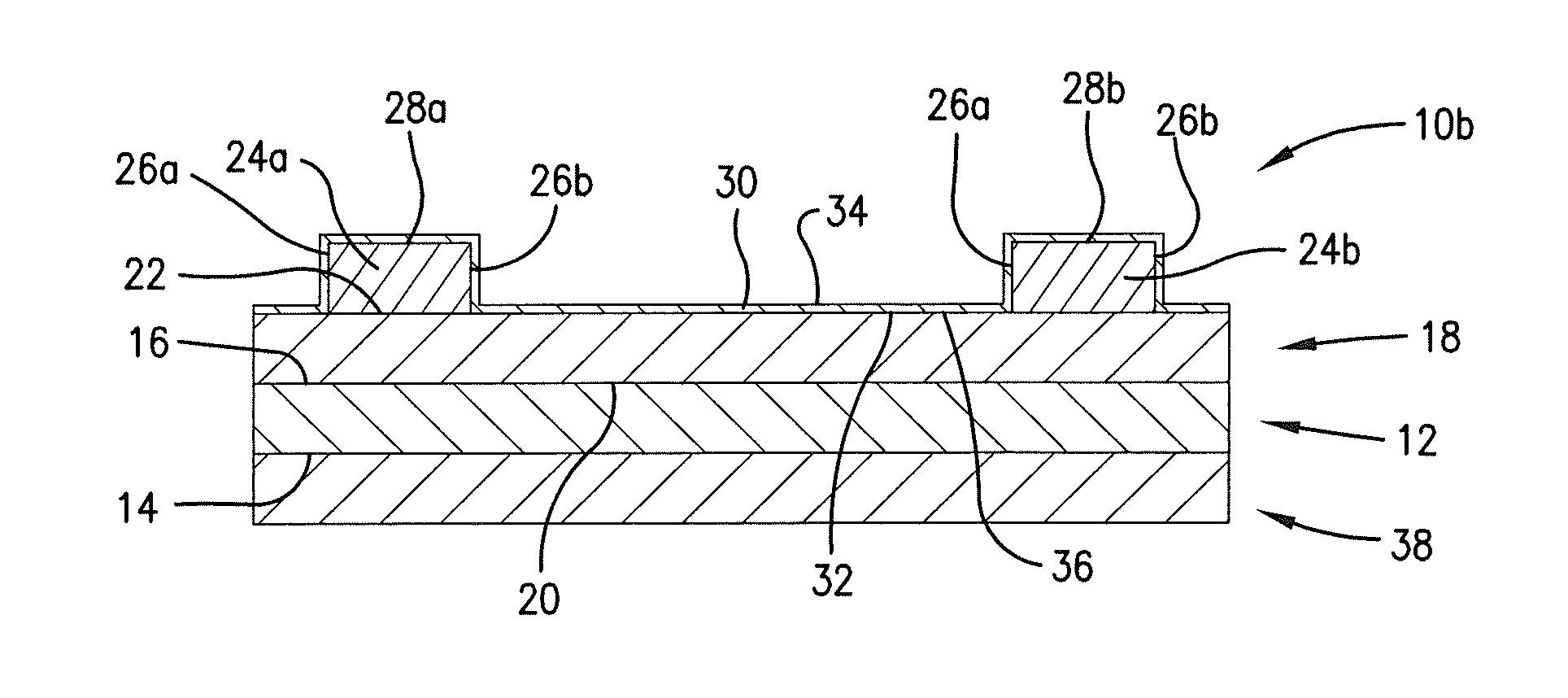
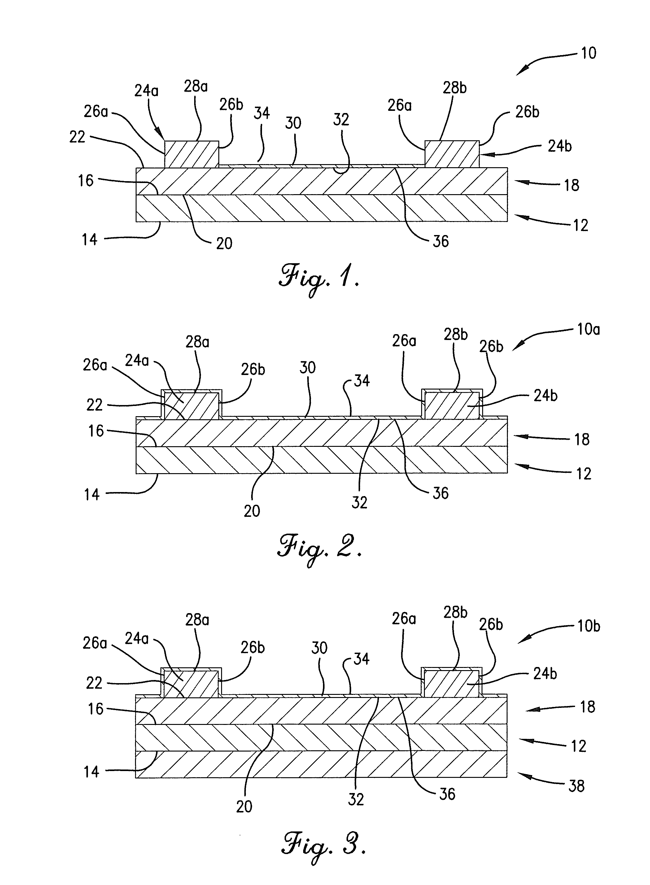
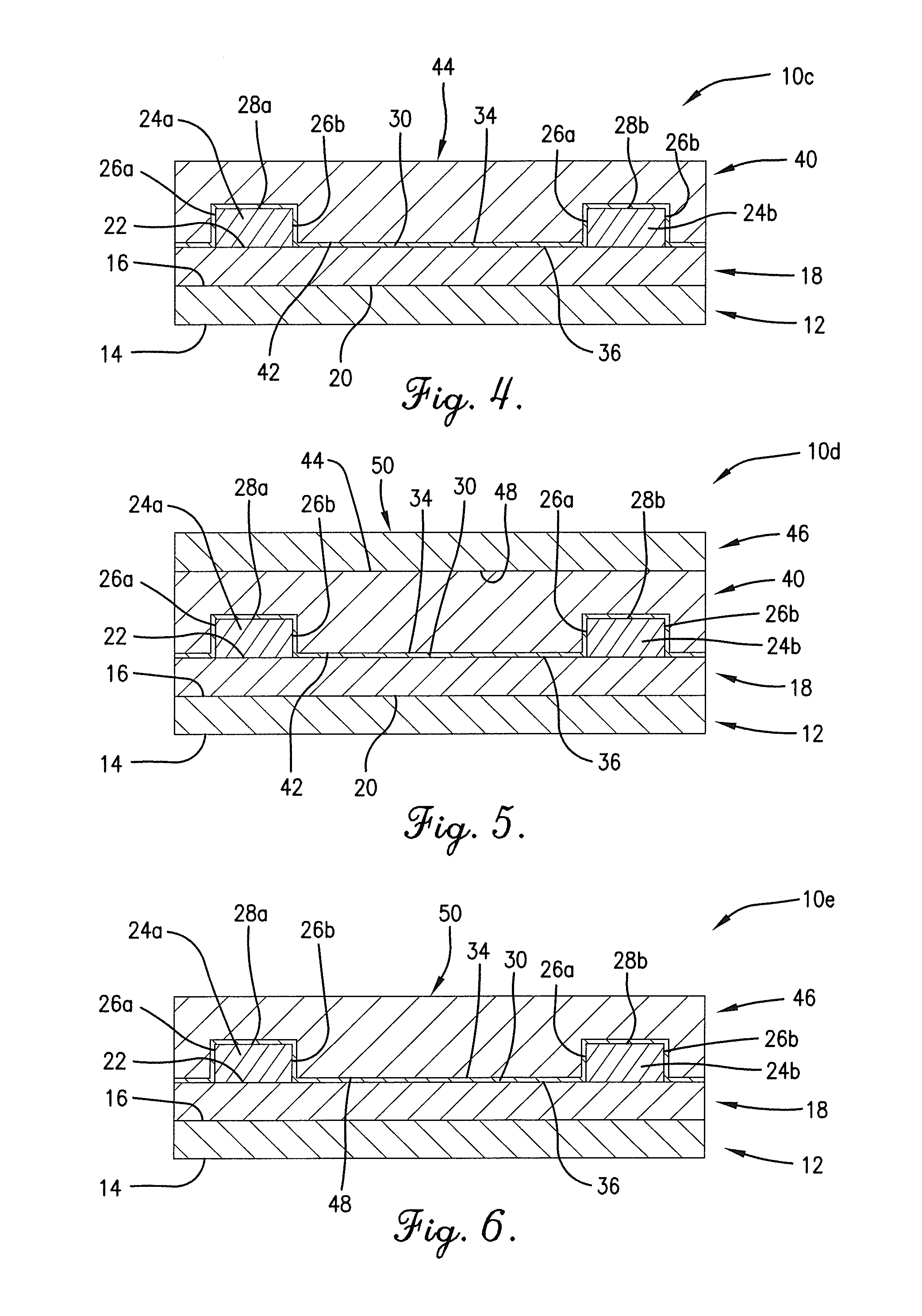
Fabrication of Integrated Temperature / Analyte Transducers on PET

[0100]In this Example, 32 integrated temperature / analyte transducers were fabricated on a flexible Melinex® ST730 PET substrate (Tekra, Inc., 16700 West Lincoln Avenue, New Berlin, Wis. 53151. The structure of the transducers is shown in FIG. 11. First, the substrate was baked in a conveyor oven at 130° C. at a 10″ / min speed. Next, a bottom metal layer, AG-800 silver conductive ink (Conductive Compounds, Hudson, N.H.), was screen printed onto the substrate using a AT-60PD screen printer using the following parameters: screen: polyester, 230 threads / inch, flood / squeegee speed: 225 mm / s, flood bar pressure: 10 psi, squeegee pressure: 25 psi. The substrate was then cured in the conveyor oven at 130° C. at a 10″ / min speed. The cured silver film had a thickness of 5 μm. A bottom insulation layer, an experimental cycloolefin polymer from Brewer Science, Inc., was screen printed on top of the metal layer using the same paramet...


PUM


Abstract

Printed resistive-based sensors and transducers comprising a thin, electronically “active” sensing layer within a dielectric and/or metallic layered structure are provided. The electronic resistance of the active sensing layer is measured during a change in the sensor environment. By utilizing a multi-layered architecture around the active sensing layer, the electronic signal of the sensing element can be improved. By carefully selecting the architecture and materials that surround the active sensing layer, the sensitivity, stability, and selectivity of the sensor to detect changes in the environment are improved. This design allows for a number of specific application areas for environmental sensing.

Description

RELATED APPLICATION[0001]This application claims the priority benefit of U.S. Provisional Patent Application No. 62 / 027,753, entitled ULTRAFAST HUMIDITY DETECTOR FOR USE IN SPEECH AND HEALTH ANALYZERS, filed Jul. 22, 2014, and U.S. Provisional Patent Application No. 62 / 172,546, entitled THIN-FILM RESISTIVE-BASED SENSOR, filed Jun. 8, 2015, each of which is incorporated by reference herein.BACKGROUND OF THE INVENTION[0002]1. Field of the Invention[0003]The present invention is broadly concerned with thin-film, resistive-based sensors.[0004]2. Description of the Prior Art[0005]Sensors able to detect environmental changes are in demand for a number of applications. Detection of changes in temperature, pressure, or various analytes in contact with the sensor (including moisture or gases in the air, etc.) is desirable for applications such as indoor and outdoor climate detection and control, process control, biometrics, medical uses, and much more. However, the usefulness of these sensor...

Claims


Application Information

Patent Timeline
Patent Type & Authority Applications(United States)
IPC IPC(8): G01D5/16
CPCG01D5/16G01K7/16G01N27/125G01N27/127G01R27/02
Inventor GIEDD, RYAN E.KAYASTHA, VIJAYAFURY, JONATHANCOX, ROBERT CHRISTIAN
Owner BREWER SCI
Why Eureka
Try Eureka