Electrically heated catalyst device

a catalyst device and catalyst technology, applied in the direction of machines/engines, mechanical equipment, separation processes, etc., can solve problems such as fusing problems, and achieve the effects of reducing electric power, preventing fusing, and reducing cracks

Inactive Publication Date: 2016-02-04
TOYOTA JIDOSHA KK
View PDF3 Cites 6 Cited by
  • Summary
  • Abstract
  • Description
  • Claims
  • Application Information

AI Technical Summary

Benefits of technology

[0013]Alternatively, the heat radiation suppression portion may be a heater that heats the wiring accommodation chamber. In this case, the electrically heated catalyst device may be further equipped with a controller that controls energization of the carrier and energization of the heater. The controller may start energizing the heater before turning off energization of the carrier, and may reduce an electric power for energizing the heater after turning off energization of the carrier. By controlling the energization of the heater in this manner, a crack can be more effectively restrained from being created in the carrier through a heat cycle.
[0014]The invention can provide an electrically heated catalyst device that restrains a crack from being created in a carrier through a heat cycle.

Problems solved by technology

As a result, there arises a problem of fusing.

Method used


Image

  • Electrically heated catalyst device
  • Electrically heated catalyst device
  • Electrically heated catalyst device

Examples


first embodiment

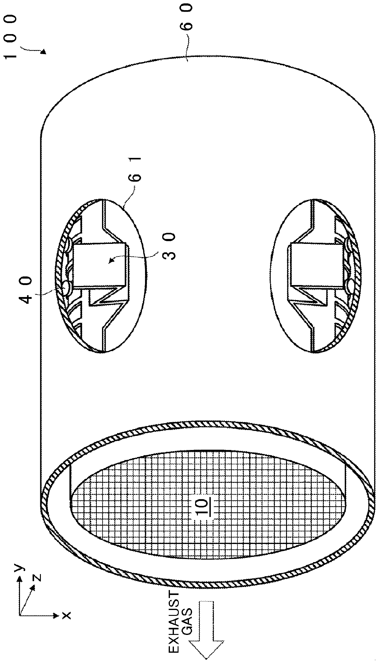
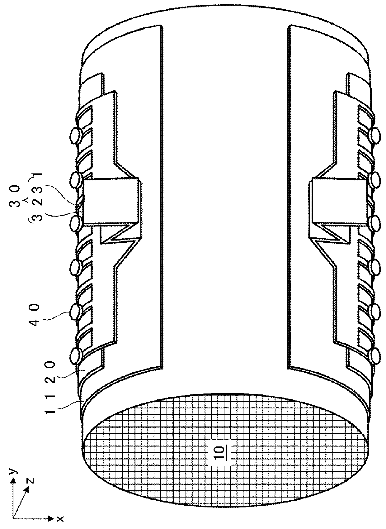
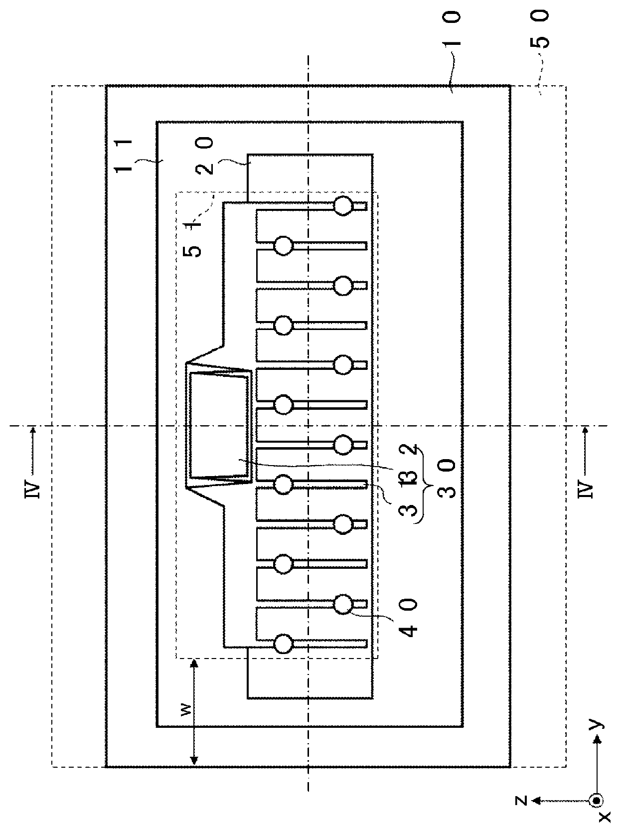
[0024]First of all, an electrically heated catalyst device according to the first embodiment of the invention will be described with reference to FIGS. 1 to 4. FIG. 1 is a perspective view of the electrically heated catalyst device according to the first embodiment of the invention. FIG. 2 is a perspective view obtained by removing the outer cylinder 60 from FIG. 1. FIG. 3 is a plan view of FIG. 2 as viewed from directly above the surface electrodes 20 (on a positive side in an x-axis direction). FIG. 4 is a cross-sectional view taken along the cutting line IV-IV of FIG. 3.

[0025]Incidentally, as a matter of course, right-handed xyz-coordinates are shown in the drawings for the sake of convenience in explaining a positional relationship among components. The xyz-coordinates are common to the respective drawings, and the axial direction of a carrier 10 is a y-axis direction. It should be noted herein that the positive side of a z-axis direction preferably coincides with an upward side...

second embodiment

[0054]Next, an electrically heated catalyst device according to the second embodiment of the invention will be described with reference to FIG. 5. FIG. 5 is a cross-sectional view of the electrically heated catalyst device according to the second embodiment of the invention. As shown in FIG. 5, with the electrically heated catalyst device according to the second embodiment of the invention, heaters 75 for heating the wiring accommodation chambers 70 are provided on outer faces of the wiring accommodation chambers 70 respectively, instead of the heat radiation suppression means 74. The heaters 75 are, for example, small-size ceramic heaters or the like. Incidentally, although the heaters 75 are stuck on outer faces of the lid portions 72 respectively in an example of FIG. 5, the heaters 75 may be stuck on outer faces of the torso portions 71 respectively. Besides, the heaters 75 may be provided apart from the wiring accommodation chambers 70 respectively. Furthermore, the heaters 75 ...


PUM


Abstract

An electrically heated catalyst device is equipped with a carrier that supports a catalyst, a pair of electric diffusion layers that are formed opposite each other on an outer peripheral face of the carrier, wiring members that are fixed to the electric diffusion layers respectively, an outer cylinder that covers an outer peripheral face of the carrier and that has, in a lateral face thereof, an opening portion through which the wiring member is pulled out to the outside, and a wiring accommodation chamber that is provided protrusively from the outer cylinder to accommodate the wiring member pulled out from the outer cylinder. The carrier is electrically heated via the wiring member. The wiring accommodation chamber is equipped with a heat radiation suppression portion for suppressing the radiation of heat from the wiring member.

Description

INCORPORATION BY REFERENCE[0001]The disclosure of Japanese Patent Application No. 2014-153971 filed on Jul. 29, 2014 including the specification, drawings and abstract is incorporated herein by reference in its entirety.BACKGROUND OF THE INVENTION[0002]1. Field of the Invention[0003]The invention relates to an electrically heated catalyst device.[0004]2. Description of Related Art[0005]In recent years, an electrically heated catalyst (EHC) device has been drawing attention as an exhaust gas control apparatus that purifies the exhaust gas discharged from an engine of an automobile or the like. Even under a condition where the temperature of exhaust gas is low and a catalyst is unlikely to be activated, for example, immediately after the start of the engine or the like, the EHC can enhance the efficiency in purifying exhaust gas by forcibly activating the catalyst through electric heating.[0006]With an EHC disclosed in Japanese Patent Application Publication No. 2013-136997 (JP 2013-1...

Claims


Application Information

Patent Timeline
Patent Type & Authority Applications(United States)
IPC IPC(8): F01N3/20B01D53/94
CPCF01N3/2013B01D53/9454B01D53/9495F01N3/18F01N3/2026F01N3/2828Y02T10/12
Inventor SUGIYAMA, NATSUKINAITO, HIDEJI
Owner TOYOTA JIDOSHA KK
Why Eureka
Try Eureka